

The mechanical effects of short-circuit currents in - Montefiore
The mechanical effects of short-circuit currents in - Montefiore
The mechanical effects of short-circuit currents in - Montefiore

Create successful ePaper yourself
Turn your PDF publications into a flip-book with our unique Google optimized e-Paper software.
6. D.C. CONFIGURATIONS<br />
6.1. INTRODUCTION<br />
A reliable power supply <strong>of</strong> substations and power plants<br />
<strong>of</strong>ten needs the construction <strong>of</strong> enlarged d.c.<br />
<strong>in</strong>stallations <strong>in</strong> which batteries act as energy storage<br />
devices. Installations without batteries are fed through<br />
converter and controlled drives. For these systems to be<br />
safe, the knowledge <strong>of</strong> <strong>short</strong>-<strong>circuit</strong> strength is required.<br />
<strong>The</strong>refore it is necessary to study the <strong>currents</strong> and forces<br />
which can occur and to develop simplified methods for<br />
design <strong>of</strong> d.c. configurations.<br />
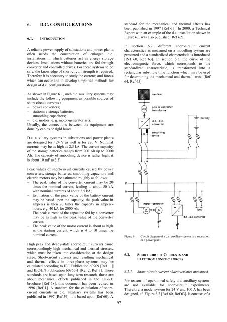
As shown <strong>in</strong> Figure 6.1, such d.c. auxiliary systems may<br />
<strong>in</strong>clude the follow<strong>in</strong>g equipment as possible sources <strong>of</strong><br />
<strong>short</strong>-<strong>circuit</strong> <strong>currents</strong> :<br />
– power converters;<br />
– stationary storage batteries;<br />
– smooth<strong>in</strong>g capacitors;<br />
– d.c. motors, e. g. motor-generator sets.<br />
Usually, the connections between the equipment are<br />
done by cables or rigid buses.<br />
D.c. auxiliary systems <strong>in</strong> substations and power plants<br />
are designed for ±24 V as well as for 220 V. Nom<strong>in</strong>al<br />
<strong>currents</strong> may be as high as 2,5 kA. <strong>The</strong> current capacity<br />
<strong>of</strong> the storage batteries ranges from 200 Ah up to 2000<br />
Ah. <strong>The</strong> capacity <strong>of</strong> smooth<strong>in</strong>g device is rather high; it<br />
is about 10 mF to 3 F.<br />
Peak values <strong>of</strong> <strong>short</strong>-<strong>circuit</strong> <strong>currents</strong> caused by power<br />
converters, storage batteries, smooth<strong>in</strong>g capacitors and<br />
electric motors may be estimated roughly as follows:<br />
– <strong>The</strong> peak value <strong>of</strong> the converter current may be 20<br />
times the nom<strong>in</strong>al current, lead<strong>in</strong>g to about 50 kA<br />
with nom<strong>in</strong>al <strong>currents</strong> <strong>of</strong> about 2,5 kA;<br />
– Estimation <strong>of</strong> the peak value <strong>of</strong> the battery current<br />
may be based upon the capacity; the peak value <strong>in</strong><br />
amperes is then 20 times the capacity <strong>in</strong> amperehours,<br />
e.g. 40 kA for 2000 Ah;<br />
– <strong>The</strong> peak current <strong>of</strong> the capacitor fed by a converter<br />
may be as high as the peak value <strong>of</strong> the converter<br />
current;<br />
– <strong>The</strong> peak value <strong>of</strong> the motor current is about as high<br />
as the start<strong>in</strong>g current, which is 4 to 10 times the<br />
nom<strong>in</strong>al current.<br />
High peak and steady-state <strong>short</strong>-<strong>circuit</strong> <strong>currents</strong> cause<br />
correspond<strong>in</strong>gly high <strong>mechanical</strong> and thermal stresses,<br />
which must be taken <strong>in</strong>to consideration at the design<br />
stage. Short-<strong>circuit</strong> <strong>currents</strong> and result<strong>in</strong>g <strong>mechanical</strong><br />
and thermal <strong>effects</strong> <strong>in</strong> three-phase systems may be<br />
calculated accord<strong>in</strong>g to IEC Publication 60909 [Ref 11]<br />
and IEC/EN Publication 60865-1 [Ref 2, Ref 3]. <strong>The</strong>se<br />
standards are based upon long-term research, those are<br />
about <strong>mechanical</strong> <strong>effects</strong> published <strong>in</strong> the CIGRE<br />
brochure [Ref 58]; this document has been revised <strong>in</strong><br />
1996 [Ref 1]. A standard for the calculation <strong>of</strong> <strong>short</strong><strong>circuit</strong><br />
<strong>currents</strong> <strong>in</strong> d.c. auxiliary systems has been<br />
published <strong>in</strong> 1997 [Ref 59], it is based upon [Ref 60]. A<br />
97<br />
standard for the <strong>mechanical</strong> and thermal <strong>effects</strong> has<br />
been published <strong>in</strong> 1997 [Ref 61]. In 2000, a Technical<br />
Report with an example <strong>of</strong> the d.c. <strong>in</strong>stallation shown <strong>in</strong><br />
Figure 6.1 was also published [Ref 62].<br />
In section 6.2, different <strong>short</strong>-<strong>circuit</strong> current<br />
characteristics as measured on a modell<strong>in</strong>g system are<br />
presented and a standardized characteristic is <strong>in</strong>troduced<br />
[Ref 60, Ref 63]. In section 6.3, the curve <strong>of</strong> the<br />
electromagnetic force, which corresponds to the<br />
standardized characteristic, is transformed <strong>in</strong>to a<br />
rectangular substitute time function which may be used<br />
for determ<strong>in</strong><strong>in</strong>g the <strong>mechanical</strong> and thermal stress [Ref<br />
64, Ref 65].<br />
Figure 6.1 Circuit diagram <strong>of</strong> a d.c. auxiliary system <strong>in</strong> a substation<br />
or a power plant.<br />
6.2. SHORT-CIRCUIT CURRENTS AND<br />
ELECTROMAGNETIC FORCES<br />
6.2.1. Short-<strong>circuit</strong> current characteristics measured<br />
For reasons <strong>of</strong> operational safety d.c. auxiliary systems<br />
are not available for <strong>short</strong>-<strong>circuit</strong> experiments.<br />
<strong>The</strong>refore, a model system for 24 V and 100 A has been<br />
designed, cf. Figure 6.2 [Ref 60, Ref 63]. It consists <strong>of</strong> a


