

The mechanical effects of short-circuit currents in - Montefiore
The mechanical effects of short-circuit currents in - Montefiore
The mechanical effects of short-circuit currents in - Montefiore

Create successful ePaper yourself
Turn your PDF publications into a flip-book with our unique Google optimized e-Paper software.
standardized characteristics for the <strong>currents</strong> and<br />
electromagnetic forces are <strong>in</strong>troduced. With this,<br />
simplified methods are derived to calculate the<br />
<strong>mechanical</strong> and thermal <strong>effects</strong> which are stated <strong>in</strong><br />
IEC 61660-1 and IEC 61660-2 [Ref 59, Ref 61].<br />
In the Annex, the equivalent static load and the<br />
equivalent static load factor are def<strong>in</strong>ed and<br />
evaluated for different k<strong>in</strong>ds <strong>of</strong> support<strong>in</strong>g and<br />
<strong>short</strong>-<strong>circuit</strong> load<strong>in</strong>g, the calculation accord<strong>in</strong>g to<br />
IEC 60865-1 are compared with test results, the<br />
<strong>in</strong>fluence <strong>of</strong> reclosure is shown and a simplified<br />
method for calculation is derived, and flow charts<br />
to the standardized method for rigid busbars is<br />
given. Errata to the brochure 105 complete this<br />
part.<br />
1.2. GENERAL PRESENTATION OF THE MAIN<br />
PROBLEM<br />
Let’s recall some basic <strong>of</strong> physics <strong>in</strong> relation with<br />
<strong>short</strong>-<strong>circuit</strong> <strong>mechanical</strong> <strong>effects</strong>, <strong>in</strong> the case <strong>of</strong> a<br />
flexible busbar. This understand<strong>in</strong>g is favourably<br />
accompanied by the observation <strong>of</strong> the video which<br />
detailed some <strong>short</strong>-<strong>circuit</strong> tests on rigid and<br />
flexible busbar (available at CIGRE central <strong>of</strong>fice).<br />
After <strong>short</strong>-<strong>circuit</strong> <strong>in</strong>ception, the flexible bus starts<br />
to sw<strong>in</strong>g. If both <strong>currents</strong> are flow<strong>in</strong>g <strong>in</strong> opposite<br />
direction (typical two-phase fault) the conductors<br />
will separate from each other. If both <strong>currents</strong> are<br />
flow<strong>in</strong>g <strong>in</strong> the same direction (two conductor <strong>of</strong> one<br />
bundle for example) the conductors will come<br />
together. After a <strong>short</strong> while, there is not only<br />
k<strong>in</strong>etic, potential and electromagnetic energy (this<br />
last disappear<strong>in</strong>g at the end <strong>of</strong> the <strong>short</strong>-<strong>circuit</strong>), but<br />
some deformation energy (elongation <strong>of</strong> the cable<br />
which causes tension fluctuations and stra<strong>in</strong> energy<br />
<strong>in</strong> support) and thermal energy (due to heat<strong>in</strong>g<br />
<strong>effects</strong>). Of course damp<strong>in</strong>g is present (structural<br />
damp<strong>in</strong>g and aerodynamic damp<strong>in</strong>g) but it is<br />
negligible at the beg<strong>in</strong>n<strong>in</strong>g compared to other<br />
energies.<br />
Thus after <strong>short</strong>-<strong>circuit</strong> <strong>in</strong>ception, there is a big<br />
mixture and exchange <strong>of</strong> energy which f<strong>in</strong>ally<br />
disappears due to damp<strong>in</strong>g.<br />
Typical maximum loads for design, generally<br />
appear when global energy has to be mostly<br />
converted <strong>in</strong>to deformation energy. This is<br />
especially the case dur<strong>in</strong>g maximum sw<strong>in</strong>g out<br />
(very low k<strong>in</strong>etic and potential energy so that a<br />
large part is converted <strong>in</strong> deformation energy,<br />
which means a large <strong>in</strong>crease <strong>of</strong> tension), the fall<strong>in</strong>g<br />
down maxima (same reason, generally more critic<br />
because <strong>of</strong> the loss <strong>of</strong> potential energy due to cable<br />
position at that moment), and the p<strong>in</strong>ch effect (same<br />
reason also, but at that time we have the full<br />
electromagnetic energy, especially dur<strong>in</strong>g<br />
asymmetrical part <strong>of</strong> the current, and the other<br />
6<br />
k<strong>in</strong>ds <strong>of</strong> energy have not yet started to take their<br />
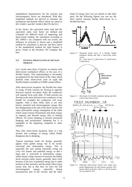
part). On the follow<strong>in</strong>g figures you can see the<br />
three typical maxima dur<strong>in</strong>g <strong>short</strong>-<strong>circuit</strong> on a<br />
flexible bus-bars.<br />
Figure 1.2 Measured tensile force <strong>of</strong> a flexible bundle<br />
conductor dur<strong>in</strong>g and after a l<strong>in</strong>e-to-l<strong>in</strong>e <strong>short</strong><strong>circuit</strong><br />
(Fst , static force, Fpi, p<strong>in</strong>ch force, Ft, tensile force,<br />
Ff drop force)<br />
Figure 1.3 Movement <strong>of</strong> a flexible conductor dur<strong>in</strong>g and after<br />
a l<strong>in</strong>e-to-l<strong>in</strong>e <strong>short</strong>-<strong>circuit</strong><br />
Figure 1.4 Schematic <strong>short</strong>-<strong>circuit</strong> current wave shape (i(t),<br />
portal displacement (d) and tension <strong>in</strong>crease (∆T)<br />
(p<strong>in</strong>ch effect) <strong>in</strong> the bus. <strong>The</strong>re is a 50 kN <strong>in</strong>crease<br />
over an <strong>in</strong>itial 8.7 kN.


