

The mechanical effects of short-circuit currents in - Montefiore
The mechanical effects of short-circuit currents in - Montefiore
The mechanical effects of short-circuit currents in - Montefiore

You also want an ePaper? Increase the reach of your titles
YUMPU automatically turns print PDFs into web optimized ePapers that Google loves.
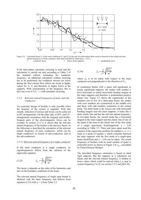
Figure 2.6 Calculated factors Vr <strong>in</strong> the outer conductors L1 and L3 <strong>in</strong> the case <strong>of</strong> a three-phase <strong>short</strong> <strong>circuit</strong> as function <strong>of</strong> the related relevant<br />
natural frequency fc/f <strong>of</strong> the conductor, both ends fixed [Ref 8]. Dead time tu = 0,3 s.<br />
1 conductor stress 2 forces on the supports 3 standardised curve<br />
If the three-phase automatic reclos<strong>in</strong>g is used and the<br />
calculation is carried out only accord<strong>in</strong>g to Table 2 <strong>of</strong><br />
the standard without estimat<strong>in</strong>g the conductor<br />
frequency, an additional calculation without reclos<strong>in</strong>g<br />
has to be performed; the conductor stresses are lower<br />
dur<strong>in</strong>g the first current flow which can result <strong>in</strong> higher<br />
values for VF Vr and therefore <strong>in</strong> higher forces at the<br />
supports. With consideration <strong>of</strong> the frequency this is<br />
also true even if VFVr > 1 with automatic reclos<strong>in</strong>g.<br />
2.2.4. Relevant natural frequencies <strong>of</strong> ma<strong>in</strong>- and subconductors<br />
An economic design <strong>of</strong> busbars is only possible when<br />
the dynamic <strong>of</strong> the system is regarded. With this<br />
remark, reduction <strong>of</strong> stresses and forces can be achieved<br />
<strong>in</strong> HV-arrangements. On the other side, <strong>in</strong> MV- and LVarrangements<br />
resonances with the frequent and doublefrequent<br />
parts <strong>of</strong> the electromagnetic forces can be<br />
avoided. In section 2.2.3 it is shown that the relevant<br />
natural frequency <strong>of</strong> the busbar is the decisive factor. In<br />
the follow<strong>in</strong>g is described the estimation <strong>of</strong> the relevant<br />
natural frequency <strong>of</strong> ma<strong>in</strong> conductors, which can be<br />
s<strong>in</strong>gle conductors or consist <strong>of</strong> sub-conductors, and <strong>of</strong><br />
the sub-conductors.<br />
2.2.4.1 Relevant natural frequency <strong>of</strong> a s<strong>in</strong>gle conductor<br />
If the ma<strong>in</strong> conductor is a s<strong>in</strong>gle conductor, its<br />
eigenfrequencies follow from the solution <strong>of</strong> the<br />
eigenvalue equation<br />
(2.33)<br />
f<br />
c i<br />
γ<br />
=<br />
l<br />
i<br />
2<br />
EJ<br />
m′<br />
<strong>The</strong> factor γi depends on the order <strong>of</strong> the harmonics and<br />
also on the boundary conditions <strong>of</strong> the beam.<br />
<strong>The</strong> relevant natural frequency <strong>of</strong> s<strong>in</strong>gle span beams is<br />
identical with the basic frequency and follows from<br />
equation (2.33) with γ1 = γ from Table 2.3:<br />
m<br />
20<br />
(2.34)<br />
f<br />
c<br />
γ<br />
=<br />
2<br />
l<br />
EJ<br />
m′<br />
where Jm is to be taken with respect to the ma<strong>in</strong><br />
conductor axis perpendicular to the direction <strong>of</strong> Fm.<br />
In cont<strong>in</strong>uous beams with n spans and equidistant or<br />
nearly equidistant supports, the modes with number n<br />
have horizontal or nearly horizontal bend<strong>in</strong>g tangent at<br />
the <strong>in</strong>ner supports and therefore a predom<strong>in</strong>ant positive<br />
elastic l<strong>in</strong>e. Figure 2.7 shows the eigenmodes <strong>of</strong> the<br />
numbers one to five <strong>of</strong> a three-span beam; the modes<br />
with even numbers are symmetrical to the middle axis<br />
and those with odd numbers symmetric to the central<br />
po<strong>in</strong>t. <strong>The</strong> third mode is the lowest one with horizontal<br />
bend<strong>in</strong>g tangent near the <strong>in</strong>ner supports, it looks like a<br />
static elastic l<strong>in</strong>e and has the relevant natural frequency.<br />
In two-span beams, the second mode has a horizontal<br />
tangent at the <strong>in</strong>ner support and the elastic l<strong>in</strong>e <strong>of</strong> one <strong>of</strong><br />
the spans is the same as the elastic l<strong>in</strong>e <strong>of</strong> the first mode<br />
<strong>of</strong> a s<strong>in</strong>gle span-beam fixed/supported: γ = 2,45<br />
accord<strong>in</strong>g to Table 2.3. Three and more spans need the<br />
solution <strong>of</strong> the eigenvalue problem for number n. n → ∞<br />
leads to a mode <strong>of</strong> number n which co<strong>in</strong>cides between<br />
the <strong>in</strong>ner supports with the first mode <strong>of</strong> a s<strong>in</strong>gle-span<br />
beam fixed/fixed and γ = 3,56 can be taken. <strong>The</strong> actual<br />
frequency <strong>of</strong> busbars with an usual number <strong>of</strong> spans is<br />
somewhat lower as shown <strong>in</strong> Figure 2.8; fc,n, calculated<br />
by F<strong>in</strong>ite-Element-Method.<br />
<strong>The</strong> described frequency estimation is based on ideal<br />
rigid supports. But the supports <strong>in</strong> a substation are<br />
elastic and the relevant natural frequency is shifted to<br />
lower values which could be noticed when fc is near to<br />
system frequency f or 2f, see section 2.2.3 and [Ref 26].<br />
m


