

The mechanical effects of short-circuit currents in - Montefiore
The mechanical effects of short-circuit currents in - Montefiore
The mechanical effects of short-circuit currents in - Montefiore

You also want an ePaper? Increase the reach of your titles
YUMPU automatically turns print PDFs into web optimized ePapers that Google loves.
3.3. THE DROPPER BEHAVIOUR<br />
3.3.1. Introduction<br />
Droppers are suspended conductors between the ma<strong>in</strong><br />
bus bars or switch-bays and apparatus, <strong>in</strong>sulator support<br />
or bush<strong>in</strong>g. <strong>The</strong>se are the typical situations B and E <strong>in</strong><br />
Figure 1.1. <strong>The</strong> dropper stress is generally very low <strong>in</strong><br />
<strong>in</strong>itial conditions, i.e. less than 1 N/mm 2 , but can be<br />
stretched dur<strong>in</strong>g <strong>short</strong>-<strong>circuit</strong> <strong>mechanical</strong> <strong>effects</strong>. Either<br />
due to ma<strong>in</strong> bus or switch-bay cable oscillations (<strong>in</strong><br />
such a case there is no need to have any current <strong>in</strong> it) or<br />
simply due to electrodynamic forces if the <strong>short</strong>-<strong>circuit</strong><br />
current is go<strong>in</strong>g through it or <strong>in</strong> comb<strong>in</strong>ation <strong>of</strong> both.<br />
In addition to stretch, droppers are also submitted to<br />
tensile force dur<strong>in</strong>g sw<strong>in</strong>g-out, drop force and p<strong>in</strong>ch<br />
effect; (<strong>in</strong> the case <strong>of</strong> bundle configuration only). Due to<br />
the very unleveled structure and very low tension <strong>in</strong> it,<br />
dropper behaviour is quite different from the ma<strong>in</strong> bus<br />
and correspond<strong>in</strong>g <strong>effects</strong> cannot be evaluated by actual<br />
IEC/EN 60865-1.<br />
Droppers, generally more than one per span, and very<br />
sensibly <strong>in</strong>fluences the ma<strong>in</strong> bus <strong>mechanical</strong> behaviour<br />
limit<strong>in</strong>g by, for example, the fall<strong>in</strong>g down <strong>effects</strong>. <strong>The</strong>ir<br />
position <strong>in</strong> the bus, moreover to practical electrical<br />
aspects for design, can be chosen to limit the <strong>short</strong><strong>circuit</strong><br />
<strong>effects</strong> <strong>in</strong> the ma<strong>in</strong> bus. But the consequence on<br />
the dropper and correspond<strong>in</strong>g loads applied at the<br />
bottom <strong>of</strong> the dropper on apparatus must be carefully<br />
evaluated.<br />
Figure 3.20 details all k<strong>in</strong>d <strong>of</strong> dropper <strong>effects</strong> used <strong>in</strong><br />
open-air substations and classifies six different<br />
configurations.<br />
dropper<br />
fixed upper ends flexible upper ends<br />
<strong>effects</strong><br />
between<br />
phases<br />
<strong>effects</strong><br />
between<br />
sub-conductors<br />
non<br />
stretched<br />
s<strong>in</strong>gle bundle s<strong>in</strong>gle bundle s<strong>in</strong>gle<br />
stretched<br />
bundle<br />
1 2 3 4 5 6<br />
Figure 3.20 Case study for dropper configuration<br />
With configurations 1 and 2 the current is always<br />
flow<strong>in</strong>g through the droppers. Configurations 3 to 5<br />
occur when <strong>short</strong>-<strong>circuit</strong> current is go<strong>in</strong>g through the<br />
droppers. When there is no current <strong>in</strong> the dropper, the<br />
dangerous situation is limited to configurations 5 and 6<br />
with stretched droppers.<br />
In this chapter all these configurations will be evaluated<br />
either by simplified, if possible, or advanced computation<br />
method, which can be used <strong>in</strong> all<br />
configurations. Experimental confrontations with<br />
advanced methods are given <strong>in</strong> section 3.3.3, with<br />
42<br />
simplified method accord<strong>in</strong>g to IEC/EN 60865-1 <strong>in</strong><br />
annex 8.3.<br />
<strong>The</strong> f<strong>in</strong>al result will be to obta<strong>in</strong> the forces Ft and Ff <strong>in</strong><br />
the bus dur<strong>in</strong>g sw<strong>in</strong>g-out and fall <strong>of</strong> the bus and its<br />
maximum horizontal displacement as well as the load<br />
Fds <strong>in</strong> the lower clamp <strong>of</strong> the dropper and its<br />
correspond<strong>in</strong>g ESL.<br />
3.3.2. Typical oscillograms<br />
a) Droppers with fixed upper ends (configurations 1 and<br />
2)<br />
A dropper can have a fixed upper end as connection E<br />
<strong>in</strong> Figure 1.1. When connection B is fastened near the<br />
<strong>in</strong>sulator str<strong>in</strong>g, the upper end will move slightly due to<br />
the movement <strong>of</strong> the span and can be treated as (nearly)<br />
fixed. Both correspond to configurations 1 and 2 <strong>in</strong><br />
Figure 3.20.<br />
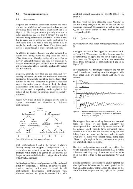
In configurations *17 for s<strong>in</strong>gle conductors and *18 for<br />
bundled conductors, oscillograms for droppers with<br />
fixed upper ends are given. Figure 3.21 shows an<br />
example.<br />
Figure 3.21 Oscillograms <strong>of</strong> horizontal components x and y <strong>of</strong> the<br />
load applied to support<strong>in</strong>g <strong>in</strong>sulator at the bottom side.<br />
Case *17, p. 79, Figure 17.2<br />
<strong>The</strong> droppers have no stretch<strong>in</strong>g because the two end<br />
po<strong>in</strong>ts are more or less fixed. Generally the<br />
electrodynamic load can be directly seen on the force. If<br />
the dropper length permits large movement, same<br />
behaviour as a ma<strong>in</strong> bus can be seen, sw<strong>in</strong>g out and<br />
fall<strong>in</strong>g down can occur, but the force value is much<br />
lower due to <strong>in</strong>itial very limited value. Some local<br />
<strong>effects</strong> i.e. right angle at the top can <strong>in</strong>duce some peaks<br />
just after <strong>short</strong>-<strong>circuit</strong> <strong>in</strong>ception.<br />
<strong>The</strong> test configuration can considerably affect the<br />
results. Especially for voltage level around 123 kV; that<br />
is because basic frequency <strong>of</strong> apparatus are close to 50<br />
or 60 Hz. This is true for test configurations *17 and<br />
*18.<br />
Bend<strong>in</strong>g stiffness <strong>of</strong> the conductors usually ignored has<br />
also significant <strong>in</strong>fluence on the loads applied at the<br />
fixation on the <strong>in</strong>sulator at the bottom. <strong>The</strong> clamp on the<br />
top <strong>of</strong> <strong>in</strong>sulator support was very rigid so that general


