

The mechanical effects of short-circuit currents in - Montefiore
The mechanical effects of short-circuit currents in - Montefiore
The mechanical effects of short-circuit currents in - Montefiore

Create successful ePaper yourself
Turn your PDF publications into a flip-book with our unique Google optimized e-Paper software.
In circular pr<strong>of</strong>iles, every axis through the center <strong>of</strong><br />
gravity can be axis <strong>of</strong> <strong>in</strong>ertia, also the drawn axis<br />
O-O <strong>in</strong> which the vector 1 2 M M M<br />
r r r<br />
= + lies and is<br />
simultaneously the neutral axis. <strong>The</strong> absolute value<br />
<strong>of</strong> M r is given by the equation (2.63):<br />
(2.63)<br />
r<br />
M = M =<br />
r<br />
M<br />
2<br />
1<br />
r<br />
+ M 2<br />
With σ1max = M1/Z, σ2max = M2/Z and σmax = M/Z the<br />
maximum stress becomes:<br />
(2.64)<br />
σ<br />
max<br />
= ±<br />
σ<br />
2<br />
1max<br />
+ σ<br />
Equation (2.64) is also valid for tubes.<br />
a)<br />
b)<br />
2<br />
2<br />
2max<br />
Figure 2.16 Stresses caused by orthogonal moments<br />
a) rectangular pr<strong>of</strong>ile<br />
b) circular pr<strong>of</strong>ile<br />
2.3. SPECIAL CONFIGURATIONS<br />
2.3.1. Associated phase structures busbar on a<br />
common support<br />
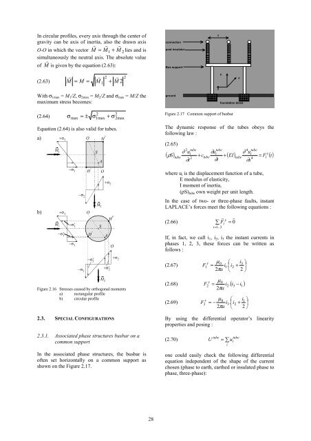
In the associated phase structures, the busbar is<br />
<strong>of</strong>ten set horizontally on a common support as<br />
shown on the Figure 2.17.<br />
28<br />
connection<br />
post <strong>in</strong>sulator<br />
Bus support<br />
ground<br />
a<br />
y<br />
z<br />
x<br />
foundation block<br />
Figure 2.17 Common support <strong>of</strong> busbar<br />
<strong>The</strong> dynamic response <strong>of</strong> the tubes obeys the<br />
follow<strong>in</strong>g law :<br />
(2.65)<br />
∂ u<br />
∂u<br />
∂ u<br />
i<br />
i<br />
i y<br />
( ρS)<br />
+ c + ( EI)<br />
= F () t<br />
tube<br />
2<br />
∂t<br />
tube<br />
2<br />
tube<br />
tube<br />
∂t<br />
tube<br />
4<br />
∂x<br />
tube<br />
where ui is the displacement function <strong>of</strong> a tube,<br />
E modulus <strong>of</strong> elasticity,<br />
I moment <strong>of</strong> <strong>in</strong>ertia,<br />
(ρS)tube own weight per unit length.<br />
In the case <strong>of</strong> two- or three-phase faults, <strong>in</strong>stant<br />
LAPLACE’s forces meet the follow<strong>in</strong>g equations :<br />
(2.66) ∑<br />
i=<br />
r<br />
y<br />
Fi<br />
1..<br />
3<br />
r<br />
= 0<br />
If, <strong>in</strong> fact, we call i1, i2, i3 the <strong>in</strong>stant <strong>currents</strong> <strong>in</strong><br />
phases 1, 2, 3, these forces can be written as<br />
follows :<br />
0 ⎛ i3<br />
⎞<br />
(2.67) F1 = i1.<br />
⎜i2<br />
+ ⎟<br />
2 a ⎝ 2 ⎠<br />
y µ<br />
π<br />
0<br />
(2.68) F i . ( i i )<br />
y<br />
−<br />
2<br />
µ<br />
=<br />
2πa<br />
0 ⎛ i1<br />
⎞<br />
(2.69) F3 = − i3.<br />
⎜i2<br />
+ ⎟<br />
2 a ⎝ 2 ⎠<br />
y µ<br />
π<br />
By us<strong>in</strong>g the differential operator’s l<strong>in</strong>earity<br />
properties and pos<strong>in</strong>g :<br />
(2.70) U ∑u<br />
2<br />
tube<br />
=<br />
i<br />
3<br />
tube<br />
i<br />
one could easily check the follow<strong>in</strong>g differential<br />
equation <strong>in</strong>dependent <strong>of</strong> the shape <strong>of</strong> the current<br />
chosen (phase to earth, earthed or <strong>in</strong>sulated phase to<br />
phase, three-phase):<br />
1<br />
4<br />
i


