

The mechanical effects of short-circuit currents in - Montefiore
The mechanical effects of short-circuit currents in - Montefiore
The mechanical effects of short-circuit currents in - Montefiore

Create successful ePaper yourself
Turn your PDF publications into a flip-book with our unique Google optimized e-Paper software.
Only the first eigenfrequencies can be compared<br />
<strong>in</strong> Figure 3.14, which shows an excellent<br />
conformity between the calculated and the<br />
measured values. <strong>The</strong> very good conformity <strong>of</strong><br />
the calculated spr<strong>in</strong>g constants and first<br />
eigenfreqencies with the measured values proves<br />
the validity <strong>of</strong> the FE model used for the<br />
simulation <strong>of</strong> the portals.<br />
Hence, all static and dynamic analyses can be<br />
performed on this model.<br />
Figure 3.14 Comparison <strong>of</strong> calculated and measured 1 st<br />
eigenfrequencies<br />
Experience has shown that, although the <strong>short</strong><strong>circuit</strong><br />
movements <strong>of</strong> stranded conductors seem<br />
to be chaotic, the relevant <strong>effects</strong> <strong>of</strong> symmetric<br />
arrangements and excitation are <strong>in</strong> fact also<br />
symmetrical. <strong>The</strong> measur<strong>in</strong>g po<strong>in</strong>ts could,<br />
therefore, be arranged to a half <strong>of</strong> the plane <strong>of</strong><br />
symmetry as shown <strong>in</strong> Figure 3.15 on crossarm,<br />
tower and bottom end <strong>of</strong> tower, i.e. <strong>in</strong>terface to<br />
foundation.<br />
In order to be able to validate and compare the<br />
measured, respectively calculated <strong>mechanical</strong><br />
stresses at the different po<strong>in</strong>ts <strong>of</strong> the structure as<br />
illustrated <strong>in</strong> Figure 3.15, the Equivalent Static<br />
Load ESL and the ESL-factors are <strong>in</strong>troduced.<br />
S<strong>in</strong>ce the <strong>short</strong>-<strong>circuit</strong> forces Fpi, Ft and Ff<br />
conta<strong>in</strong> the static pre-load the ESL-factor is to be<br />
def<strong>in</strong>ed as the quotient <strong>of</strong> the Equivalent Static<br />
Load divided by the <strong>short</strong>-<strong>circuit</strong> load <strong>in</strong>clud<strong>in</strong>g<br />
the static pre-load.<br />
40<br />
Figure 3.15 Stra<strong>in</strong> gauge measur<strong>in</strong>g po<strong>in</strong>ts <strong>in</strong> the South portal<br />
S<strong>in</strong>ce it is possible to separate the static pre-load and<br />
the dynamic part <strong>of</strong> Fpi, Fb Ff, one can, also def<strong>in</strong>e<br />
another type <strong>of</strong> ESL related to the dynamic portion<br />
alone. S<strong>in</strong>ce the static pre-Ioad is a particularly<br />
important parameter for the magnitude <strong>of</strong> Fpi, this<br />
other def<strong>in</strong>ition is more suited and practical for the<br />
dynamic portion <strong>of</strong> the sw<strong>in</strong>g-out and the conductorfall<br />
maximum. In the present context the <strong>in</strong>dex d -for<br />
dynamic -is employed <strong>in</strong> ESLd and ESLd Factor.<br />
<strong>The</strong> evaluation <strong>of</strong> the present tests does not<br />
explicitly dist<strong>in</strong>guish between sw<strong>in</strong>g-out and<br />
conductor-fall ESL, the relevant <strong>short</strong>-<strong>circuit</strong> test<br />
maxima be<strong>in</strong>g sw<strong>in</strong>g-out (Index t), and the<br />
conductor drop- p<strong>in</strong>g tests deliver<strong>in</strong>g ESLf anyway.<br />
Because <strong>of</strong> the s<strong>in</strong>gle conductors there is no p<strong>in</strong>ch<br />
effect, i.e. no Fpi.<br />
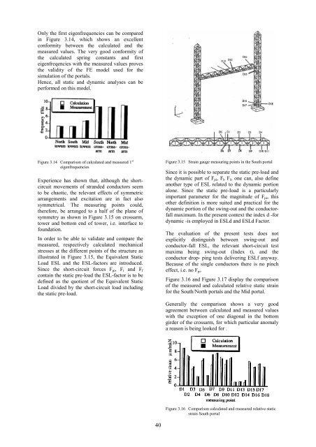
Figure 3.16 and Figure 3.17 display the comparison<br />
<strong>of</strong> the measured and calculated relative static stra<strong>in</strong><br />
for the South/North portals and the Mid portal.<br />
Generally the comparison shows a very good<br />
agreement between calculated and measured values<br />
with the exception <strong>of</strong> one diagonal <strong>in</strong> the bottom<br />
girder <strong>of</strong> the crossarm, for which particular anomaly<br />
a reason is be<strong>in</strong>g looked for .<br />
Figure 3.16 Comparison calculated and measured relative static<br />
stra<strong>in</strong> South portal


