The mechanical effects of short-circuit currents in - Montefiore
The mechanical effects of short-circuit currents in - Montefiore
The mechanical effects of short-circuit currents in - Montefiore
Create successful ePaper yourself
Turn your PDF publications into a flip-book with our unique Google optimized e-Paper software.
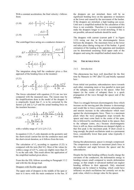
With a constant acceleration, the f<strong>in</strong>al velocity v follows<br />
from:<br />
a 1 2 1 v<br />
y x − = & y&<br />
ta<br />
= t<br />
2 2 2 t<br />
(3.18) ( ) 2 a<br />
(3.19)<br />
y<br />
v = 2<br />
a<br />
−<br />
2<br />
t<br />
( x)<br />
<strong>The</strong> centrifugal force act<strong>in</strong>g on a conductor element is<br />
m′<br />
d xv<br />
d F =<br />
y<br />
(3.20)<br />
( x)<br />
− a / 2 y(<br />
x)<br />
m′<br />
⎡<br />
= 4 y<br />
t ⎢<br />
⎣<br />
a<br />
2<br />
=<br />
a ⎤<br />
2⎥<br />
⎦<br />
a<br />
( x)<br />
− d x<br />
a<br />
⎡<br />
y<br />
m′<br />
d x ⎢<br />
⎢2<br />
− a / 2 ⎢<br />
⎢⎣<br />
a ⎤<br />
−<br />
2 ⎥<br />
⎥<br />
ta<br />
⎥<br />
⎥⎦<br />
( x)<br />
<strong>The</strong> <strong>in</strong>tegration along half the conductor gives a first<br />
approach <strong>of</strong> the bend<strong>in</strong>g force at the <strong>in</strong>sulator:<br />
(3.21)<br />
F<br />
v<br />
K<br />
2<br />
K<br />
2<br />
m′<br />
⎡<br />
= ∫ d F = 4 y<br />
t ∫ ⎢<br />
⎣<br />
0<br />
a<br />
0<br />
( x)<br />
a ⎤ K µ 0<br />
− d x 4<br />
2⎥<br />
=<br />
⎦ 6 2π<br />
( I ′′ )<br />
<strong>The</strong> forces calculated with equation (3.21) are too low<br />
compared with the measured ones. <strong>The</strong> reason may be<br />
the simplifications done <strong>in</strong> the model <strong>of</strong> the dropper. It<br />
is empirically found that Fv is to be corrected by the<br />
factors ld/K and 2,5 ld/b and the actual bend<strong>in</strong>g force on<br />
the <strong>in</strong>sulator becomes :<br />
ld<br />
ld<br />
K µ 0<br />
Fd<br />
= Fv<br />
2,<br />
5 = 4<br />
b K 6 2π<br />
(3.22)<br />
2<br />
5 µ 0 ( I k′′<br />
) ld<br />
= ld<br />
3 2π<br />
a b<br />
( I ′′ )<br />
with a validity range <strong>of</strong> 1,4 ≤ ld/b ≤ 3,3.<br />
k<br />
a<br />
2<br />
k<br />
a<br />
ld<br />
ld<br />
2,<br />
5<br />
b K<br />
In equation (3.22), Fd only depends on the geometry and<br />
the <strong>short</strong>-<strong>circuit</strong> current but not the conductor mass and<br />
the <strong>short</strong>-<strong>circuit</strong> duration, as it follows from the tests.<br />
<strong>The</strong> calculation <strong>of</strong> Fd accord<strong>in</strong>g to equation (3.22) is<br />
compared with the tests [Ref 41]. Most <strong>of</strong> the values lie<br />
with<strong>in</strong> a range <strong>of</strong> ±25 %, some are slightly more than 25<br />
% on the safe side. This result allows the application <strong>of</strong><br />
the simplified method given above.<br />
From this the ESL follows accord<strong>in</strong>g to Paragraph 3.5.2<br />
and with this the design load.<br />
Droppers with flexible upper ends<br />
<strong>The</strong> upper ends <strong>of</strong> droppers <strong>in</strong> the middle <strong>of</strong> the span or<br />
near to it move with the ma<strong>in</strong> conductor <strong>in</strong> the bus. If<br />
2<br />
2<br />
52<br />
the droppers are not stretched, there will be no<br />
significant bend<strong>in</strong>g force on the apparatus or <strong>in</strong>sulators<br />
at the lower end caused by the movement <strong>of</strong> the busbar.<br />
If the droppers are stretched, a high load<strong>in</strong>g can occur.<br />
Until now a simplified method for the calculation <strong>of</strong> this<br />
force is not available. <strong>The</strong>refore it is recommended to<br />
make the droppers longer to avoid stretch<strong>in</strong>g. If this is<br />
not possible, advanced methods should be used.<br />
<strong>The</strong> droppers with current (current path C <strong>in</strong> Figure<br />
3.22) sw<strong>in</strong>g out due to the electromagnetic forces<br />
between the droppers. <strong>The</strong> maximum force at the lower<br />
end takes place dur<strong>in</strong>g sw<strong>in</strong>g-out <strong>of</strong> the busbar. A good<br />
estimation <strong>of</strong> the load<strong>in</strong>g at the apparatus and <strong>in</strong>sulators<br />
can be determ<strong>in</strong>ed assum<strong>in</strong>g fixed upper ends <strong>of</strong> the<br />
droppers and us<strong>in</strong>g the simplified method stated above.<br />
3.4. THE BUNDLE PINCH<br />
3.4.1. Introduction<br />
This phenomena has been well described for the first<br />
time by Manuzio <strong>in</strong> 1967 [Ref 53] and briefly repeated<br />
here :<br />
From <strong>in</strong>itial rest position, subconductors move towards<br />
each other, rema<strong>in</strong><strong>in</strong>g more or less parallel <strong>in</strong> most part<br />
<strong>of</strong> the subspan, except close to the spacer. After first<br />
impact (<strong>in</strong> the centre <strong>of</strong> subspan) there is a quick<br />
propagation <strong>of</strong> the wave through the spacer end <strong>of</strong> the<br />
subspan.<br />
<strong>The</strong>re is a struggle between electromagnetic force which<br />
<strong>in</strong>crease on the mov<strong>in</strong>g part (the distance is decreas<strong>in</strong>g)<br />
and would like to force contact between subconductors,<br />
and tension <strong>in</strong>crease <strong>in</strong> the subconductor which react<br />
aga<strong>in</strong>st the electromagnetic force. <strong>The</strong>re is a maximum<br />
p<strong>in</strong>ch when the wave propagation stops towards the<br />
spacer and must come back to the centre <strong>of</strong> the span,<br />
this is followed by oscillations (back to the spacer, then<br />
to the subspan centre, etc.) because electromagnetic<br />
force is still on, these oscillations are damped slightly so<br />
that first peak is the maximum peak. If <strong>short</strong> <strong>circuit</strong> is<br />
long enough, the p<strong>in</strong>ch oscillations tends to a permanent<br />
force, considerably lower than peak value (typically 2<br />
times less).<br />
Dur<strong>in</strong>g this phenomenon, spacer is strongly compressed.<br />
<strong>The</strong> compression is related to maximum p<strong>in</strong>ch force <strong>in</strong><br />
the conductor and angle between the spacer and the<br />
subconductor.<br />
Despite the fact that bend<strong>in</strong>g stiffness locally change the<br />
curvature <strong>of</strong> the conductors, the deformation energy <strong>in</strong><br />
bend<strong>in</strong>g rema<strong>in</strong> small compared to tensile deformation<br />
energy, so that simple or advanced method can neglect<br />
bend<strong>in</strong>g stiffness <strong>in</strong> their approach. Only structural<br />
damp<strong>in</strong>g can be related to bend<strong>in</strong>g, which could have<br />
<strong>in</strong>fluence on p<strong>in</strong>ch oscillations but certa<strong>in</strong>ly not on the<br />
peak value, which is a design value for the spacer.


