

The mechanical effects of short-circuit currents in - Montefiore
The mechanical effects of short-circuit currents in - Montefiore
The mechanical effects of short-circuit currents in - Montefiore

Create successful ePaper yourself
Turn your PDF publications into a flip-book with our unique Google optimized e-Paper software.
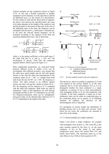
Typical examples are the conductors shown <strong>in</strong> Figure<br />
2.11a. At one end a flexible connection to another<br />
equipment can be fastened, or <strong>in</strong> the span there could be<br />
an additional mass, e.g. the contact <strong>of</strong> a disconnector.<br />
For the cantilever ends and the drawn k<strong>in</strong>d <strong>of</strong> supports,<br />
the factor γ lies between the specified limits; the value<br />
to be taken depends on the lengths <strong>of</strong> the cantilever end<br />
and the freedom <strong>of</strong> movement <strong>of</strong> that end. In the case <strong>of</strong><br />
the additional mass <strong>in</strong> the span, the frequency can be<br />
calculated with the factor cm stated above. Alternatively,<br />
<strong>in</strong> all cases the relevant natural frequency can be<br />
estimated accord<strong>in</strong>g to the equation (2.38) from the<br />
maximum displacement max y due to dead load:<br />
(2.46)<br />
f<br />
c<br />
=<br />
=<br />
1<br />
2π<br />
1<br />
2π<br />
cF<br />
≈<br />
m<br />
F<br />
mg<br />
n<br />
1<br />
2π<br />
gn<br />
=<br />
max y<br />
1 F<br />
m max y<br />
1<br />
2π<br />
gn<br />
max y<br />
where cF is the spr<strong>in</strong>g coefficient, m the overall mass, F<br />
the dead load due to m and gn = 9,81 m/s 2 the<br />
acceleration <strong>of</strong> gravity. From this the numerical<br />
equation follows which is given <strong>in</strong> Figure 2.11.<br />
More complicated connections, e.g. swan-neck bends<br />
between different levels <strong>in</strong> Figure 2.11b, can be<br />
<strong>in</strong>vestigated with sufficient accuracy. Lets assume that<br />
the sides have equal lengths and are full stiff aga<strong>in</strong>st<br />
torsion; <strong>in</strong> this case the static l<strong>in</strong>e perpendicular to the<br />
conductor plane for ϕ = 180°, i.e. straight beam both<br />
ends fixed, fits also for 90° ≤ ϕ < 180°, the frequency is<br />
correct. <strong>The</strong> other extreme is no stiffness aga<strong>in</strong>st<br />
torsion, the sides will sag like cantilever beams for ϕ =<br />
90°; the frequency will be reduced to 63 % compared<br />
with the ideal stiff conductor. Both limits are used <strong>in</strong><br />
substations: Tubes <strong>in</strong> HV-substations are stiff whereas<br />
rectangular pr<strong>of</strong>iles <strong>in</strong> MV- LV-substations are not stiff.<br />
For frequency-estimation, tubes can be ‘straightened’<br />
and good results can be obta<strong>in</strong>ed after reduction <strong>of</strong> 5 %<br />
to 15 % depend<strong>in</strong>g on the length <strong>of</strong> the sides .<br />
24<br />
a)<br />
b)<br />
clamp, cabel<br />
flexible jo<strong>in</strong>t<br />
mass <strong>of</strong> disconnector-contact<br />
A<br />
B<br />
ϕ<br />
max y<br />
1,57 < γ < 2,46<br />
2,46 < γ < 3,56<br />
alternatively:<br />
fc 5<br />
≈<br />
Hz max y<br />
cm<br />
sectional view AB:<br />
displacements<br />
Figure 2.11 Estimation <strong>of</strong> relevant frequency<br />
a) Cantilever beam and beam with<br />
additional masses<br />
b) swan-neck bend<br />
2.2.5. Section moduli <strong>of</strong> ma<strong>in</strong> and sub-conductors<br />
<strong>The</strong> stresses σm and σs accord<strong>in</strong>g to equations (2.5) and<br />
(2.6) depend on the section moduli Zm <strong>of</strong> the ma<strong>in</strong><br />
conductor and Zs <strong>of</strong> the sub-conductor. For Zm it is to<br />
dist<strong>in</strong>guish whether the ma<strong>in</strong> conductor is a s<strong>in</strong>gle<br />
conductor, or consists <strong>of</strong> two or more sub-conductors<br />
with rectangular pr<strong>of</strong>ile or <strong>of</strong> two sub-conductors with<br />
U-pr<strong>of</strong>ile. If the ma<strong>in</strong> conductor is made up <strong>of</strong> subconductors,<br />
there can be either no connect<strong>in</strong>g piece or<br />
the connect<strong>in</strong>g pieces act as spacers or as stiffen<strong>in</strong>g<br />
elements. In addition, the direction <strong>of</strong> the<br />
electromagnetic force is important.<br />
For calculation <strong>of</strong> section moduli the distribution <strong>of</strong><br />
bend<strong>in</strong>g stresses has to be taken <strong>in</strong>to account. Axial<br />
forces do not occur, the conductors are assumed to<br />
move free <strong>in</strong> the clamps.<br />
2.2.5.1 Section modulus <strong>of</strong> a s<strong>in</strong>gle conductor<br />
Figure 2.12a shows a s<strong>in</strong>gle conductor, for example<br />
with rectangular cross section Am. <strong>The</strong> vector m Mr is the<br />
outer moment caused by the force Fm on the ma<strong>in</strong><br />
conductor. It lies <strong>in</strong> the centre Sm and makes<br />
compressive stress above the neutral fibre O-O and<br />
tensile stress below. <strong>The</strong> maximum stress σm <strong>in</strong> the<br />
outer fibres at ±dm/2 follows from equation (2.25)


