- Page 1 and 2:
http://researchspace.auckland.ac.nz
- Page 3 and 4:
UNIVERSITV OF AUCKI'AND Abstract -
- Page 5 and 6:
There was no significant difference
- Page 7 and 8:
This is Dedicated: Dedication To th
- Page 9 and 10:
New Zealand The Paediatric Departme
- Page 11 and 12:
Contents Abstract ........tr Dedica
- Page 13 and 14:
6.5.4 The subjects............... .
- Page 15 and 16:
XIV
- Page 17 and 18:
List of Figures Figure l.l: Top l0
- Page 19 and 20:
List of Abbreviations ABPA allergic
- Page 21 and 22:
LADA N*N* dimethyl L-arginine LFA1
- Page 23 and 24:
t}ryem(eNoS)Typeltrendothelialnifti
- Page 25 and 26:
area, some of it has been expanded
- Page 27 and 28:
In addition, both of these groups a
- Page 29 and 30:
studies conducted throughout the Un
- Page 31 and 32:
Video clips of infants with a varie
- Page 33 and 34:
the Paediatric Society of New 7*ala
- Page 35 and 36:
inhaled anti-cholinergic agents and
- Page 37 and 38:
ecommended to monitor asthma at hom
- Page 39 and 40:
improvement to 70Vo PEF would have
- Page 41 and 42:
Furthermore, investigators have als
- Page 43 and 44:
poorer predictor of a diagnosis of
- Page 45 and 46:
Bronsky et al. 1998), and a long-te
- Page 47 and 48:
SIGN guideline (SIGN 2005) stated "
- Page 49 and 50:
In brief, the human airway can be d
- Page 51 and 52:
The ability to biopsy has led to st
- Page 53 and 54:
small proportion of cells recovered
- Page 55 and 56:
methodology of sputum induction and
- Page 57 and 58:
et al. 1999; Giannini, Di Franco et
- Page 59 and 60:
over a six month treatment prograrn
- Page 61 and 62:
There are other studies suggesting
- Page 63 and 64:
So is induced sputum in adults and
- Page 65 and 66:
asymptomatic patients independent o
- Page 67 and 68:
onchial hyper-responsiveness (Reich
- Page 69 and 70:
led to research which looked for le
- Page 71 and 72:
analyser machines. This thesis pres
- Page 73 and 74:
The pollution of the 'great smog of
- Page 75 and 76:
adults greater than 65 years (Ostro
- Page 77 and 78:
levels compared to those children l
- Page 79 and 80:
More recently 'Air Quality Indexes'
- Page 81 and 82:
acetylcholine. These were known to
- Page 83 and 84:
cyclase does not produce significan
- Page 85 and 86: Garthwaite l99l), and the non adren
- Page 87 and 88: significant complication, this trea
- Page 89 and 90: locus for the enzyme is a susceptib
- Page 91 and 92: NO synthesis and in so doing blocke
- Page 93 and 94: 3.1 Chapter 3: The synthesis, react
- Page 95 and 96: BHa = tetrahyrobiopterin, FAD = fla
- Page 97 and 98: (Knowles, McWeeny et al. 1974) and
- Page 99 and 100: more potent at low oxygen tensions
- Page 101 and 102: toxic products such as isoprostanes
- Page 103 and 104: Figure 3.3: The nitric oxide syntha
- Page 105 and 106: providing NO as a neurotransmitter
- Page 107 and 108: The enzyme of this second pathway -
- Page 109 and 110: inappropriate production from comme
- Page 111 and 112: Nicotinamide adenosine dinucleotide
- Page 113 and 114: enzyme and are competitively revers
- Page 115 and 116: 4.1 Introduction Chapter 4: Methods
- Page 117 and 118: 4.4 Nitrite and nitrate The measure
- Page 119 and 120: insensitive (Braker and Mossman 197
- Page 121 and 122: A group of instruments have been de
- Page 123 and 124: The original group demonstrated tha
- Page 125 and 126: equired it. For example, there was
- Page 127 and 128: helium for 30 minutes to remove Oz.
- Page 129 and 130: (Postlethwait and Bidani 1990; Post
- Page 131 and 132: is set at 5ppm (AIHA 1966) based on
- Page 133 and 134: 5.1 Chapter 5: Methodological asses
- Page 135: wanted to compare the patterns of e
- Page 139 and 140: an advisor for this work and main s
- Page 141 and 142: Delay time: the time between turnin
- Page 143 and 144: led to an increased water content t
- Page 145 and 146: Chapter 6: Methodological studies o
- Page 147 and 148: pulmonary circulation appeared to c
- Page 149 and 150: al found levels of 10.3ppb compared
- Page 151 and 152: Authors and Pap€r Sublect numbers
- Page 153 and 154: only those measured by mouth or low
- Page 155 and 156: 6. Check that the pens work. Fill w
- Page 157 and 158: keys but it is currently in the mid
- Page 159 and 160: Calibration pressures: the test por
- Page 161 and 162: T-piece: tO The first figure shows
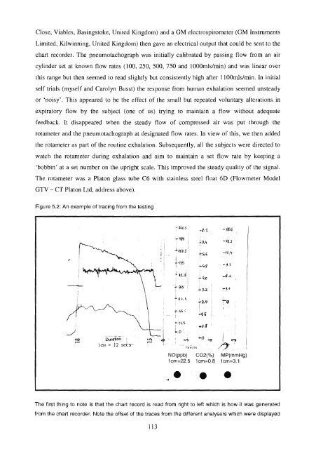
- Page 163 and 164: the rotameter. Tracings of each par
- Page 165 and 166: Figure 6.6: Mean exhaled NO levels
- Page 167 and 168: NO and COz results from single exha
- Page 169 and 170: 6.6.4 (iii) Comparison of exhaled n
- Page 171 and 172: Figure 6.11b: COz levels at peak NO
- Page 173 and 174: I also considered whether the diffe
- Page 175 and 176: the direct to the indirect method l
- Page 177 and 178: need for methodological experiments
- Page 179 and 180: The exhalations were carried out in
- Page 181 and 182: Figure 7.2: Example of the tracing
- Page 183 and 184: 7.4.4 Results There was an increase
- Page 185 and 186: Table 7.3: NO, COz and duration of
- Page 187 and 188:
The second set of exhalations invol
- Page 189 and 190:
Figure 7.6: Photographs of the chan
- Page 191 and 192:
Table 7.5: Exhaled NO results with
- Page 193 and 194:
the NO concentrations taken pre and
- Page 195 and 196:
Figure 7.10: Hyperbolic relationshi
- Page 197 and 198:
pressure over the likely range enco
- Page 199 and 200:
subjects with respiratory disease,
- Page 201 and 202:
8.1 Chapter 8: Exhaled nitric oxide
- Page 203 and 204:
standard error of the mean (SEM), s
- Page 205 and 206:
T-piece sampling system to analyser
- Page 207 and 208:
Figure 8.2a: Comparison of peak exh
- Page 209 and 210:
if yes who? if yes who? if yes who?
- Page 211 and 212:
There are limitations with regard t
- Page 213 and 214:
significantly between research grou
- Page 215 and 216:
controls. Kharitinov et al reported
- Page 217 and 218:
direct method in asthmatic children
- Page 219 and 220:
Figure 8.4a: The eftect of commenci
- Page 221 and 222:
had last used her p2 agonist inhale
- Page 223 and 224:
higher level of exhaled NO at 4.9pp
- Page 225 and 226:
9.1 Introduction Chapter 9: Exhaled
- Page 227 and 228:
For the oral measurements options i
- Page 229 and 230:
Table 9.1: The recommended standard
- Page 231 and 232:
taken from the available literature
- Page 233 and 234:
compartment correlated with the ser
- Page 235 and 236:
measurement with variable expirator
- Page 237 and 238:
to settle. We may have been measuri
- Page 239 and 240:
9.5 Off-line measurement NO determi
- Page 241 and 242:
(Hyde, Geigel et al. 1997; Tsoukias
- Page 243 and 244:
9.6 Nasal nitric oxide measurement
- Page 245 and 246:
measured over two 24 hour periods,
- Page 247 and 248:
women who coincidently experienced
- Page 249 and 250:
While these cross-sectional and the
- Page 251 and 252:
symptoms. Steroid response was sign
- Page 253 and 254:
'difficult asthma' also had higher
- Page 255 and 256:
season and then reduced down to bas
- Page 257 and 258:
of cross sectional studies with a t
- Page 259 and 260:
Ciabattoni et al. 2004; Petersen, A
- Page 261 and 262:
FEV9.5, symptom score and airways r
- Page 263 and 264:
Indomethacin - This medication alte
- Page 265 and 266:
89Vo for PCD, and above that exclud
- Page 267 and 268:
This low NO occurs despite higher t
- Page 269 and 270:
patients were followed through one
- Page 271 and 272:
differences noted based on filter,
- Page 273 and 274:
9.L6 Nitric oxide levels in exercis
- Page 275 and 276:
another study of 111 school childre
- Page 277 and 278:
Almost all studies used sedation, w
- Page 279 and 280:
peak exhaled NO production in the f
- Page 281 and 282:
flow and to minimize nasal contamin
- Page 283 and 284:
ecruit blood vessels in the lung. S
- Page 285 and 286:
Chapter 10: Reflections The outcome
- Page 287 and 288:
and I enrolled 52 asthmatic childre
- Page 289 and 290:
Edwards EA, Douglas C, Broome S, Je
- Page 291 and 292:
o Cass Byrnes & Nicky Holt. "Drugs
- Page 293 and 294:
o Byrnes CA. Paediatric fibreoptic
- Page 295 and 296:
Appendix 2: Questionnaire for enrol
- Page 297 and 298:
Al-Ali, M. K. and P. H. Howarth (20
- Page 299 and 300:
Archer, S. L., P. J. Shultz, et al.
- Page 301 and 302:
Baraldi, E., N. M. Azzolin, et al.
- Page 303 and 304:
Belda, J., P. Hussack, et al. (2001
- Page 305 and 306:
Bongers, T. and B. R. ODriscoll (20
- Page 307 and 308:
Brown, G. C. and C. E. Cooper (1994
- Page 309 and 310:
Castro-Rodriguez, J. A., C. J. Holb
- Page 311 and 312:
Cockcroft, D. W., D. N. Killian, et
- Page 313 and 314:
de Blic, J., V. Marchac, et al. (20
- Page 315 and 316:
Donaldson, S. H., W. D. Bennett, et
- Page 317 and 318:
Emi-Miwa, M., A. Okitani, et al. (1
- Page 319 and 320:
Frey, U., J. Stocks, et al. (2000).
- Page 321 and 322:
Gershman, N. H., H. Liu, et al. (19
- Page 323 and 324:
Grasemann, H., E. Michler, et al. (
- Page 325 and 326:
Hashimoto, T., K. Minoguchi, et al.
- Page 327 and 328:
Holgate, S. T., D. E. Davies, et al
- Page 329 and 330:
Iriso, R., P. M. Mudido, et al. (20
- Page 331 and 332:
Jones, A. W., M. Fransson, et al. (
- Page 333 and 334:
Kercsmar, C. M. (2006). Wheezing in
- Page 335 and 336:
Kleinert, H., T. Wallerath, et al.
- Page 337 and 338:
Lamblin, C., P. Gosset, et al. (199
- Page 339 and 340:
Li, X. and J. W. Wilson (1997). "In
- Page 341 and 342:
Lymar, S. V. and J. K. Hurst (1996)
- Page 343 and 344:
Massaro, A. F., S. Mehta, et al. (1
- Page 345 and 346:
Miyabara, Y., R. Yanagisawa, et al.
- Page 347 and 348:
contribute to impaired endothelium-
- Page 349 and 350:
ODell, T. J., R. D. Hawkins, et al.
- Page 351 and 352:
Panza, J. A., C. E. Garcia, et al.
- Page 353 and 354:
Peters, S. P. (2006). "Safety of in
- Page 355 and 356:
Prieto, L., L. Bruno, et al. (2003)
- Page 357 and 358:
Ribbons, K. A., X. J. Zhang, et al.
- Page 359 and 360:
Sacco, O., R. Sale, et al. (2003).
- Page 361 and 362:
Sessa, W. C., K. Pritchard, et al.
- Page 363 and 364:
Silvestri, M., F. Sabatini, et al.
- Page 365 and 366:
Stamler, J. S. (1994). "Redox signa
- Page 367 and 368:
Stuehr, D. J., N. S. Kwon, et al. (
- Page 369 and 370:
Tierney, W. M., J. F. Roesner, et a
- Page 371 and 372:
Upchurch, G. R., G. N. Welch, et al
- Page 373 and 374:
Wadsworth, R., E. Stankevicius, et
- Page 375 and 376:
Williams, O., R. Y. Bhat, et al. (2
- Page 377 and 378:
Yates, D. H., S. A. Kharitonov, et