SolarEdge
SolarEdge Installation Guide â MAN-01-00057-2.3
SolarEdge Installation Guide â MAN-01-00057-2.3

You also want an ePaper? Increase the reach of your titles
YUMPU automatically turns print PDFs into web optimized ePapers that Google loves.
Appendix D: Connecting the AC and DC Strings to the DC Safety Unit<br />
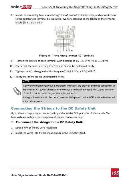
8. Insert the remaining four wires through the AC conduit to the inverter, and connect them<br />
to the appropriate terminal blocks in the inverter according to the labels on the terminal<br />
blocks (N, L1, L2 and L3).<br />
Figure 40: Three Phase Inverter AC Terminals<br />
9. Tighten the screws of each terminal with a torque of 1.2-1.5 N*m / 0.88-1.1 lb*ft.<br />
10. Check that the wires are fully inserted and cannot be pulled out easily.<br />
11. Tighten the AC cable gland with a torque of 2.8-3.3 N*m / 2.0-2.4 lb*ft.<br />
12. Verify that there are no unconnected wires.<br />
NOTE<br />
If power control is enabled, it is important to respect the order of grid lines connection to<br />
the inverter. A 120deg phase difference should be kept between L1 to L2 and between<br />
L2 to L3 (L1-L2-L3 and not, for example L1-L3-L2).<br />
If the grid lines are not in this order, an error is displayed on the LCD and the inverter will<br />
not produce power.<br />
Connecting the Strings to the DC Safety Unit<br />
Up to three strings may be connected in parallel to the DC input pairs of the switch. The<br />
terminals are suitable for connection of copper conductors only.<br />
To connect the strings to the DC Safety Unit:<br />
1. Strip 8 mm of the DC wire insulation.<br />
2. Insert the wires into the DC input glands in the DC Safety Unit.<br />
<strong>SolarEdge</strong>-Installation Guide MAN-01-00057-3.1<br />
105