SolarEdge
SolarEdge Installation Guide â MAN-01-00057-2.3
SolarEdge Installation Guide â MAN-01-00057-2.3

You also want an ePaper? Increase the reach of your titles
YUMPU automatically turns print PDFs into web optimized ePapers that Google loves.
Mounting the Inverter<br />
• AC output: AC cable external gauge:<br />
o Single phase inverters: PG21 (9-16mm diameter)<br />
o<br />
Three phase inverters: M32 (15-21mm diameter)<br />
• DC inputs: For connection of the PV installation<br />
CAUTION!<br />
Do not remove the six screws on the DC metal panel as it may<br />
harm the inverter sealing and void the warranty.<br />
• ON/OFF switch: Turning this switch ON starts the operation of the power optimizers,<br />
enables power production and allows the inverter to begin exporting power to the<br />
utility grid. Turning it OFF reduces the power optimizer voltage to a low safety voltage<br />
and inhibits exportation of power. When this switch is OFF, the inverter control<br />
circuitry remains powered up.<br />
• LCD light button: Pressing this button lights up the LCD for 30 seconds. In addition, you<br />
can press this button to access configuration menu options, as described Configuring<br />
the Inverter Using the LCD Light Button on page 39.<br />
• Two communication glands, for connection of inverter communication options. Each<br />
gland has three openings. Refer to Setting Up Communication on page 55 for more<br />
information.<br />
Mounting the Inverter<br />
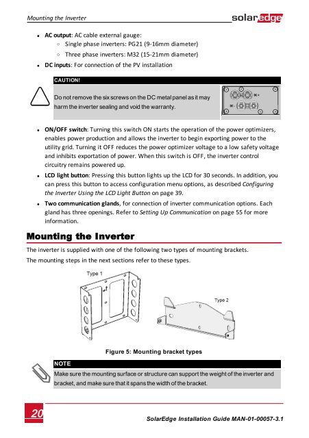
The inverter is supplied with one of the following two types of mounting brackets.<br />
The mounting steps in the next sections refer to these types.<br />
Figure 5: Mounting bracket types<br />
NOTE<br />
Make sure the mounting surface or structure can support the weight of the inverter and<br />
bracket, and make sure that it spans the width of the bracket.<br />
20<br />
<strong>SolarEdge</strong>-Installation Guide MAN-01-00057-3.1