SolarEdge
SolarEdge Installation Guide â MAN-01-00057-2.3
SolarEdge Installation Guide â MAN-01-00057-2.3

You also want an ePaper? Increase the reach of your titles
YUMPU automatically turns print PDFs into web optimized ePapers that Google loves.
Chapter 7: Setting Up Communication<br />
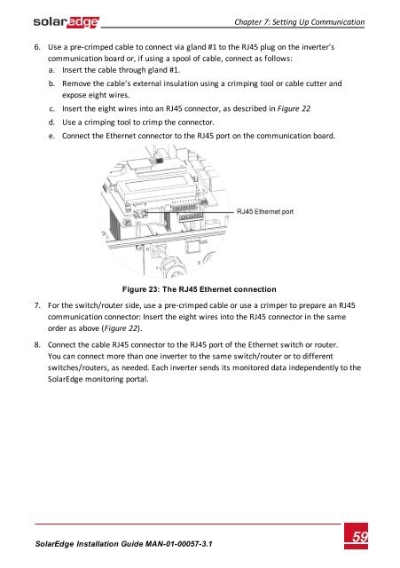
6. Use a pre-crimped cable to connect via gland #1 to the RJ45 plug on the inverter's<br />
communication board or, if using a spool of cable, connect as follows:<br />
a. Insert the cable through gland #1.<br />
b. Remove the cable’s external insulation using a crimping tool or cable cutter and<br />
expose eight wires.<br />
c. Insert the eight wires into an RJ45 connector, as described in Figure 22<br />
d. Use a crimping tool to crimp the connector.<br />
e. Connect the Ethernet connector to the RJ45 port on the communication board.<br />
Figure 23: The RJ45 Ethernet connection<br />
7. For the switch/router side, use a pre-crimped cable or use a crimper to prepare an RJ45<br />
communication connector: Insert the eight wires into the RJ45 connector in the same<br />
order as above (Figure 22).<br />
8. Connect the cable RJ45 connector to the RJ45 port of the Ethernet switch or router.<br />
You can connect more than one inverter to the same switch/router or to different<br />
switches/routers, as needed. Each inverter sends its monitored data independently to the<br />
<strong>SolarEdge</strong> monitoring portal.<br />
<strong>SolarEdge</strong>-Installation Guide MAN-01-00057-3.1<br />
59