SolarEdge
SolarEdge Installation Guide â MAN-01-00057-2.3
SolarEdge Installation Guide â MAN-01-00057-2.3

You also want an ePaper? Increase the reach of your titles
YUMPU automatically turns print PDFs into web optimized ePapers that Google loves.
Chapter 7: Setting Up Communication<br />
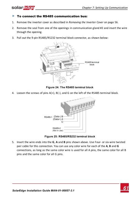
To connect the RS485 communication bus:<br />
1. Remove the inverter cover as described in Removing the Inverter Cover on page 56.<br />
2. Remove the seal from one of the openings in communication gland #2 and insert the wire<br />
through the opening.<br />
3. Pull out the 9-pin RS485/RS232 terminal block connector, as shown below:<br />
Figure 24: The RS485 terminal block<br />
4. Loosen the screws of pins A(+), B(-), and G on the left of the RS485 terminal block.<br />
Figure 25: RS485/RS232 terminal block<br />
5. Insert the wire ends into the G, A and B pins shown above. Use Four- or six-wire twisted<br />
pair cable for this connection. You can use any color wire for each of the A, B and G<br />
connections, as long as the same color wire is used for all A pins, the same color for all B<br />
pins and the same color for all G pins.<br />
<strong>SolarEdge</strong>-Installation Guide MAN-01-00057-3.1<br />
61