SolarEdge
SolarEdge Installation Guide â MAN-01-00057-2.3
SolarEdge Installation Guide â MAN-01-00057-2.3

Create successful ePaper yourself
Turn your PDF publications into a flip-book with our unique Google optimized e-Paper software.
Step 1: Activating the System<br />
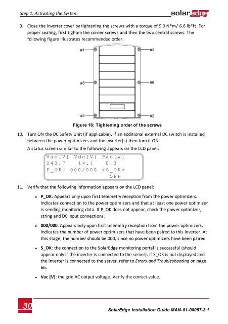
9. Close the inverter cover by tightening the screws with a torque of 9.0 N*m/ 6.6 lb*ft. For<br />
proper sealing, first tighten the corner screws and then the two central screws. The<br />
following figure illustrates recommended order:<br />
Figure 16: Tightening order of the screws<br />
10. Turn ON the DC Safety Unit (if applicable). If an additional external DC switch is installed<br />
between the power optimizers and the inverter(s) then turn it ON.<br />
A status screen similar to the following appears on the LCD panel:<br />
V a c [ V ] V d c [ V ] P a c [ w ]<br />
2 4 0 . 7 1 4 . 1 0 . 0<br />
P _ O K : 0 0 0 / 0 0 0 < S _ O K ><br />
- - - - - - - - - - - - - - - O F F<br />
11. Verify that the following information appears on the LCD panel:<br />
• P_OK: Appears only upon first telemetry reception from the power optimizers.<br />
Indicates connection to the power optimizers and that at least one power optimizer<br />
is sending monitoring data. If P_OK does not appear, check the power optimizer,<br />
string and DC input connections.<br />
• 000/000: Appears only upon first telemetry reception from the power optimizers.<br />
Indicates the number of power optimizers that have been paired to this inverter. At<br />
this stage, the number should be 000, since no power optimizers have been paired.<br />
• S_OK: the connection to the <strong>SolarEdge</strong> monitoring portal is successful (should<br />
appear only if the inverter is connected to the server). If S_OK is not displayed and<br />
the inverter is connected to the server, refer to Errors and Troubleshooting on page<br />
66.<br />
• Vac [V]: the grid AC output voltage. Verify the correct value.<br />
30<br />
<strong>SolarEdge</strong>-Installation Guide MAN-01-00057-3.1