SolarEdge
SolarEdge Installation Guide â MAN-01-00057-2.3
SolarEdge Installation Guide â MAN-01-00057-2.3

You also want an ePaper? Increase the reach of your titles
YUMPU automatically turns print PDFs into web optimized ePapers that Google loves.
Chapter 7: Setting Up Communication<br />
Chapter 7: Setting Up Communication<br />
Power optimizers send information to the inverter via the DC power lines (the PV output<br />
circuit). The information is sent from the inverter to the <strong>SolarEdge</strong> monitoring portal through<br />
the Internet. In order to send the data from the inverter, a communication connection must be<br />
set up, as described in this chapter. Communication setup is not required for power<br />
harvesting, however is needed for using the <strong>SolarEdge</strong> monitoring portal.<br />
This chapter describes setting up communication between multiple inverterss for a<br />
master/slave configuration.<br />
CAUTION!<br />
When connecting the communication cables, make sure that the ON/OFF switch at<br />
the bottom of the inverter is turned OFF, and the AC is turned OFF.<br />
When configuring the communication parameters, make sure that the ON/OFF<br />
switch is OFF, and the AC is turned ON.<br />
Communication Types<br />
• Ethernet: used for a LAN connection<br />
• RS485: used for the connection of multiple <strong>SolarEdge</strong> devices on the same bus in a<br />
master-slave configuration. RS485 type can also be used as an interface to external<br />
non-<strong>SolarEdge</strong> devices, such as revenue meters and data loggers.<br />
• ZigBee: Optional wireless communication (purchased separately; refer to the supplied<br />
manual).<br />
• Wi-Fi: Optional wireless connection (purchased separately; refer to the supplied<br />
manual).<br />
Only communication products offered by <strong>SolarEdge</strong> are supported.<br />
Always connect the communication options when the inverter is OFF.<br />
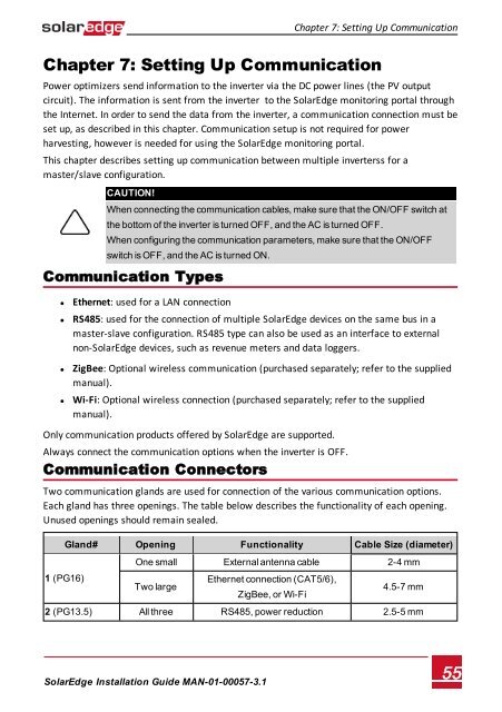
Communication Connectors<br />
Two communication glands are used for connection of the various communication options.<br />
Each gland has three openings. The table below describes the functionality of each opening.<br />
Unused openings should remain sealed.<br />
1 (PG16)<br />
Gland# Opening Functionality Cable Size (diameter)<br />
One small External antenna cable 2-4 mm<br />
Two large<br />
Ethernet connection (CAT5/6),<br />
ZigBee, or Wi-Fi<br />
4.5-7 mm<br />
2 (PG13.5) All three RS485, power reduction 2.5-5 mm<br />
<strong>SolarEdge</strong>-Installation Guide MAN-01-00057-3.1<br />
55