SolarEdge
SolarEdge Installation Guide â MAN-01-00057-2.3
SolarEdge Installation Guide â MAN-01-00057-2.3

You also want an ePaper? Increase the reach of your titles
YUMPU automatically turns print PDFs into web optimized ePapers that Google loves.
Creating an Ethernet (LAN) Connection<br />
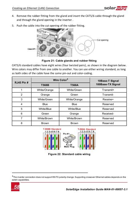
4. Remove the rubber fitting from the gland and insert the CAT5/6 cable through the gland<br />
and through the gland opening in the inverter .<br />
5. Push the cable into the cut opening of the rubber fitting.<br />
Figure 21: Cable glands and rubber fitting<br />
CAT5/6 standard cables have eight wires (four twisted pairs), as shown in the diagram below.<br />
Wire colors may differ from one cable to another. You can use either wiring standard, as long<br />
as both sides of the cable have the same pin-out and color-coding.<br />
RJ45 Pin #<br />
T568B<br />
Wire Color 1<br />
T568A<br />
10Base-T Signal<br />
100Base-TX Signal<br />
1 White/Orange White/Green Transmit+<br />
2 Orange Green Transmit-<br />
3 White/Green White/Orange Receive+<br />
4 Blue Blue Reserved<br />
5 White/Blue White/Blue Reserved<br />
6 Green Orange Received-<br />
7 White/Brown White/Brown Reserved<br />
8 Brown Brown Reserved<br />
Figure 22: Standard cable wiring<br />
1 The inverter connection does not support RX/TX polarity change. Supporting crossover Ethernet cables depends on the<br />
switch capabilities.<br />
58<br />
<strong>SolarEdge</strong>-Installation Guide MAN-01-00057-3.1