SolarEdge
SolarEdge Installation Guide â MAN-01-00057-2.3
SolarEdge Installation Guide â MAN-01-00057-2.3

Create successful ePaper yourself
Turn your PDF publications into a flip-book with our unique Google optimized e-Paper software.
Step 4: Verifying Proper Power Optimizer Connection<br />
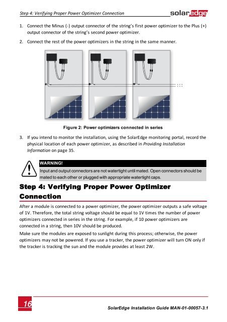
1. Connect the Minus (-) output connector of the string’s first power optimizer to the Plus (+)<br />
output connector of the string’s second power optimizer.<br />
2. Connect the rest of the power optimizers in the string in the same manner.<br />
Figure 2: Power optimizers connected in series<br />
3. If you intend to monitor the installation, using the <strong>SolarEdge</strong> monitoring portal, record the<br />
physical location of each power optimizer, as described in Providing Installation<br />
Information on page 35.<br />
WARNING!<br />
Input and output connectors are not watertight until mated. Open connectors should be<br />
mated to each other or plugged with appropriate watertight caps.<br />
Step 4: Verifying Proper Power Optimizer<br />
Connection<br />
After a module is connected to a power optimizer, the power optimizer outputs a safe voltage<br />
of 1V. Therefore, the total string voltage should be equal to 1V times the number of power<br />
optimizers connected in series in the string. For example, if 10 power optimizers are<br />
connected in a string, then 10V should be produced.<br />
Make sure the modules are exposed to sunlight during this process; otherwise, the power<br />
optimizers may not be powered. If you use a tracker, the power optimizer will turn ON only if<br />
the tracker is tracking the sun and the module provides at least 2W.<br />
16<br />
<strong>SolarEdge</strong>-Installation Guide MAN-01-00057-3.1