SolarEdge
SolarEdge Installation Guide â MAN-01-00057-2.3
SolarEdge Installation Guide â MAN-01-00057-2.3

Create successful ePaper yourself
Turn your PDF publications into a flip-book with our unique Google optimized e-Paper software.
Chapter 7: Setting Up Communication<br />
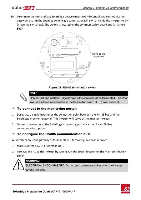
10. Terminate the first and last <strong>SolarEdge</strong> device (inverter/SMI/Control and communication<br />
gateway, etc.) in the chain by switching a termination DIP-switch inside the inverter to ON<br />
(move the switch up). The switch is located on the communication board and is marked<br />
SW7.<br />
NOTE<br />
Figure 27: RS485 termination switch<br />
Only the first and last <strong>SolarEdge</strong> devices in the chain should be terminated. The other<br />
inverters in the chain should have the termination switch OFF (down position).<br />
To connect to the monitoring portal:<br />
1. Designate a single inverter as the connection point between the RS485 bus and the<br />
<strong>SolarEdge</strong> monitoring portal. This inverter will serve as the master inverter.<br />
2. Connect the master to the <strong>SolarEdge</strong> monitoring portal via the LAN or ZigBee<br />
communication option.<br />
To configure the RS485 communication bus:<br />
All inverters are configured by default as slaves. If reconfiguration is required:<br />
1. Make sure the ON/OFF switch is OFF.<br />
2. Turn ON the AC to the inverter by turning ON the circuit breaker on the main distribution<br />
panel.<br />
WARNING!<br />
ELECTRICAL SHOCK HAZARD. Do not touch uninsulated wires when the inverter<br />
cover is removed.<br />
<strong>SolarEdge</strong>-Installation Guide MAN-01-00057-3.1<br />
63