

Cutler-Hammer - Eaton Canada
Cutler-Hammer - Eaton Canada
Cutler-Hammer - Eaton Canada

Create successful ePaper yourself
Turn your PDF publications into a flip-book with our unique Google optimized e-Paper software.
Drawings<br />
INSTALLATION<br />
AF93/IS903 Instruction Manual<br />
2-32<br />
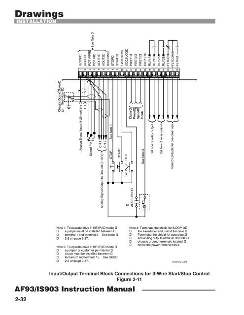
Chassis Gound Screw<br />
See Note 3<br />
ILOOP<br />
AGND<br />
POT WPR<br />
1<br />
2<br />
3<br />
4<br />
5<br />
6<br />
7<br />
8<br />
9<br />
10<br />
11<br />
12<br />
13<br />
14<br />
15<br />
16<br />
17<br />
18<br />
19<br />
20<br />
21<br />
22<br />
(+)Analog Signal Input-(4-20 mA)<br />
Speed Pot<br />
STOP<br />
Note 1: To operate drive in KEYPAD mode,<br />
a jumper must be installed between<br />
terminal 7 and terminal 8. See table<br />
2-2 on page 2-37.<br />
Note 2: To operate drive in KEYPAD mode,<br />
a jumper or customer permissive<br />
circuit must be installed between<br />
terminal 7 and terminal 15. See table<br />
2-2 on page 2-37.<br />
(Ð)<br />
See Note 3<br />
POT HI<br />
AOUT1<br />
CH 1<br />
AOUT2<br />
DIGCOM<br />
Analog Signal Output to Ground (0-10 V)<br />
CH 2<br />
STOP<br />
START<br />
FWD/REV<br />
See Note 1<br />
START<br />
ACC2/JOG<br />
PRST1<br />
REV<br />
FWD<br />
Digital<br />
Preset<br />
Speed<br />
Inputs<br />
ACCEL2/JOG<br />
PRST2<br />
PRST3<br />
EXTFLT<br />
See Note 2<br />
RLY1A<br />
RLY1B<br />
Set one of relay output<br />
RLY2A<br />
RLY2B<br />
Set two of relay output<br />
FLTNC<br />
FLTCOM<br />
Form C contacts for customer use<br />
FLTNO<br />
Note 3: Terminate the shield for ILOOP at<br />
the transducer end, not at the drive.<br />
Terminate the shield for speed pot<br />
and analog outputs at the AF93/IS903<br />
chassis ground terminals located<br />
below the power terminal block.<br />
AF93-I/O Conn<br />
Input/Output Terminal Block Connections for 3-Wire Start/Stop Control<br />
Figure 2-11


