- Page 1 and 2:
advanced building skins 14 | 15 Jun
- Page 3 and 4:
Editorial advanced building skins -
- Page 5 and 6:
ABS_07 Lucio Blandini Timo Schmidt
- Page 7 and 8:
Prof. Dr.nat.techn. Oliver Englhard
- Page 9 and 10:
Advanced Building Skins Figure 3: A
- Page 11 and 12:
2.2 Geometrical Processing Advanced
- Page 13 and 14:
3 Digital Data Advanced Building Sk
- Page 15 and 16:
4 References Advanced Building Skin
- Page 17 and 18:
Advanced Building Skins 2 The Creat
- Page 19 and 20:
Advanced Building Skins Figure 5: f
- Page 21 and 22:
Advanced Building Skins The next st
- Page 23 and 24:
Advanced Building Skins The Kilden
- Page 25 and 26:
2.1 Maintenance Advanced Building S
- Page 27 and 28:
4.2 Fire Protection Advanced Buildi
- Page 29 and 30:
7 Acknowledgements Advanced Buildin
- Page 31 and 32:
2 Cable-Stayed Glass Façade Advanc
- Page 33 and 34:
Advanced Building Skins The outer s
- Page 35 and 36:
Advanced Building Skins Figure 10:
- Page 37 and 38:
Advanced Building Skins Figure 1 a
- Page 39 and 40:
Advanced Building Skins Figure 5: S
- Page 41 and 42:
Advanced Building Skins Figure 11:
- Page 43 and 44:
Prof. Dr.nat.techn. Oliver Englhard
- Page 45 and 46:
Advanced Building Skins Figure 2: H
- Page 47 and 48:
4.1 Schüco Aluminium Window System
- Page 49 and 50:
Advanced Building Skins 5 Installat
- Page 51 and 52:
Advanced Building Skins Figure 1: B
- Page 53 and 54:
Advanced Building Skins Another pro
- Page 55 and 56:
2.2 Variety of Solutions Advanced B
- Page 57 and 58:
Advanced Building Skins Air exchang
- Page 59 and 60:
Advanced Building Skins Bq/m 3 in t
- Page 61 and 62:
Advanced Building Skins Usually the
- Page 63 and 64:
Advanced Building Skins Figure 5: T
- Page 65 and 66:
10 References Advanced Building Ski
- Page 67 and 68:
Advanced Building Skins Figure 1: P
- Page 69 and 70:
Advanced Building Skins Likewise, a
- Page 71 and 72:
3.2 Method Advanced Building Skins
- Page 73 and 74:
Advanced Building Skins 3.4 Sensiti
- Page 75 and 76:
Advanced Building Skins Figure 9: V
- Page 77 and 78:
Prof. Dr.nat.techn. Oliver Englhard
- Page 79 and 80:
Advanced Building Skins Planning te
- Page 81 and 82:
Insulation material Glass wool boar
- Page 83 and 84:
Primary energy, non renewable kWh p
- Page 85 and 86:
Advanced Building Skins timber fram
- Page 87 and 88:
Prof. Dr.nat.techn. Oliver Englhard
- Page 89 and 90:
Advanced Building Skins Figure 1: C
- Page 91 and 92:
Advanced Building Skins 2.1 Interna
- Page 93 and 94: 2.2.2 ÖGNB (TQB) Advanced Building
- Page 95 and 96: Advanced Building Skins Again the p
- Page 97 and 98: Advanced Building Skins Table 1: As
- Page 99 and 100: Advanced Building Skins [6] Interna
- Page 101 and 102: Prof. Dr.nat.techn. Oliver Englhard
- Page 103 and 104: 3 Examples 3.1 Reiss Façade, Londo
- Page 105 and 106: Advanced Building Skins properties
- Page 107 and 108: Prof. Dr.nat.techn. Oliver Englhard
- Page 109 and 110: Advanced Building Skins tensile str
- Page 111 and 112: Advanced Building Skins Deep drawin
- Page 113 and 114: Advanced Building Skins Ellipsoid o
- Page 115 and 116: Advanced Building Skins 4.3 Creatio
- Page 117 and 118: Prof. Dr.nat.techn. Oliver Englhard
- Page 119 and 120: Advanced Building Skins Figure 2: N
- Page 121 and 122: Advanced Building Skins Of the two
- Page 123 and 124: Advanced Building Skins correspond
- Page 125 and 126: 8 References Advanced Building Skin
- Page 127 and 128: Advanced Building Skins 1 Shells in
- Page 129 and 130: a) A.3a. Selection of segments A.4a
- Page 131 and 132: 4.1 Material Properties Advanced Bu
- Page 133 and 134: 5 Connecting Methods Advanced Build
- Page 135 and 136: Prof. Dr.nat.techn. Oliver Englhard
- Page 137 and 138: 5 Innovative Material Use 5.1 Struc
- Page 139 and 140: Advanced Building Skins Figure 5: S
- Page 141 and 142: 8 Conclusion Advanced Building Skin
- Page 143: Prof. Dr.nat.techn. Oliver Englhard
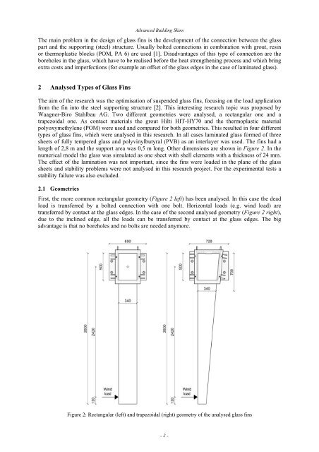
- Page 147 and 148: 3.1 Rectangular Glass Fins Advanced
- Page 149 and 150: Advanced Building Skins Figure 9 sh
- Page 151 and 152: Prof. Dr.nat.techn. Oliver Englhard
- Page 153 and 154: Advanced Building Skins 3 Design Me
- Page 155 and 156: Advanced Building Skins This compar
- Page 157 and 158: Advanced Building Skins weight plus
- Page 159 and 160: Advanced Building Skins For the fra
- Page 161 and 162: 8 References Advanced Building Skin
- Page 163 and 164: Advanced Building Skins round court
- Page 165 and 166: Advanced Building Skins 4 Cone 5 -
- Page 167 and 168: Advanced Building Skins Y Z Figure
- Page 169 and 170: Prof. Dr.nat.techn. Oliver Englhard
- Page 171 and 172: 1.2 Mapping Advanced Building Skins
- Page 173 and 174: Advanced Building Skins Figure 2: A
- Page 175 and 176: Advanced Building Skins In addition
- Page 177 and 178: Advanced Building Skins process und
- Page 179 and 180: Prof. Dr.nat.techn. Oliver Englhard
- Page 181 and 182: Advanced Building Skins does not co
- Page 183 and 184: Advanced Building Skins such materi
- Page 185 and 186: Advanced Building Skins reduced. Th
- Page 187 and 188: Advanced Building Skins Due to its
- Page 189 and 190: Prof. Dr.nat.techn. Oliver Englhard
- Page 191 and 192: Advanced Building Skins Compared t
- Page 193 and 194: Test number Inlet temperature [°C]
- Page 195 and 196:
Advanced Building Skins The next se
- Page 197 and 198:
Prof. Dr.nat.techn. Oliver Englhard
- Page 199 and 200:
Rdd [-] 0.50 0.45 0.40 0.35 0.30 0.
- Page 201 and 202:
E [kWh/m²/ ° Advanced Building Sk
- Page 203 and 204:
+110 +100 West +80 +120 +70 +60 +13
- Page 205 and 206:
3 Summary Advanced Building Skins T
- Page 207 and 208:
1 Introduction Advanced Building Sk
- Page 209 and 210:
Advanced Building Skins facade. The
- Page 211 and 212:
Advanced Building Skins Figure 4: T
- Page 213 and 214:
5 Photometric investigations Advanc
- Page 215 and 216:
Prof. Dr.nat.techn. Oliver Englhard
- Page 217 and 218:
1.3 A Closed Facade Area of 32 % Ad
- Page 219 and 220:
Advanced Building Skins 1.5 Closed-
- Page 221 and 222:
Advanced Building Skins Second Part
- Page 223 and 224:
Prof. Dr.nat.techn. Oliver Englhard
- Page 225 and 226:
Advanced Building Skins This assump
- Page 227 and 228:
Advanced Building Skins The require
- Page 229 and 230:
Advanced Building Skins Figure 7: T
- Page 231 and 232:
Advanced Building Skins Figure 9: I
- Page 233 and 234:
Prof. Dr.nat.techn. Oliver Englhard
- Page 235 and 236:
Advanced Building Skins Figure 3: K
- Page 237 and 238:
Advanced Building Skins Hartenaugas
- Page 239 and 240:
Prof. Dr.nat.techn. Oliver Englhard
- Page 241 and 242:
Advanced Building Skins 2.2 Determi
- Page 243 and 244:
Performance Condition Advanced Buil
- Page 245 and 246:
Advanced Building Skins 5 Cable Net
- Page 247 and 248:
5.4 Glass Clamp Connector Advanced
- Page 249 and 250:
Advanced Building Skins Figure 14:
- Page 251 and 252:
Advanced Building Skins elasto-plas
- Page 253 and 254:
Example projects include: Advanced
- Page 255 and 256:
Advanced Building Skins Figure 4: L
- Page 257 and 258:
Advanced Building Skins Language ba
- Page 259 and 260:
3 Summary and Conclusion Advanced B
- Page 261 and 262:
GENERAL PROPERTIES WEIGHT MORPHABIL
- Page 263 and 264:
Advanced Building Skins Regarding t
- Page 265 and 266:
Advanced Building Skins applied to
- Page 267 and 268:
4 Comparison Advanced Building Skin
- Page 269 and 270:
5 Conclusion Advanced Building Skin
- Page 271 and 272:
Advanced Building Skins Façades a
- Page 273 and 274:
Advanced Building Skins The deforma
- Page 275 and 276:
Advanced Building Skins In this cas
- Page 277 and 278:
Advanced Building Skins The interna
- Page 279 and 280:
Advanced Building Skins Because the
- Page 281 and 282:
Advanced Building Skins designers.
- Page 283 and 284:
Advanced Building Skins anchor poin
- Page 285 and 286:
Advanced Building Skins In a first