advanced building skins 14 | 15 June 2012 - lamp.tugraz.at - Graz ...
advanced building skins 14 | 15 June 2012 - lamp.tugraz.at - Graz ...
advanced building skins 14 | 15 June 2012 - lamp.tugraz.at - Graz ...

Create successful ePaper yourself
Turn your PDF publications into a flip-book with our unique Google optimized e-Paper software.
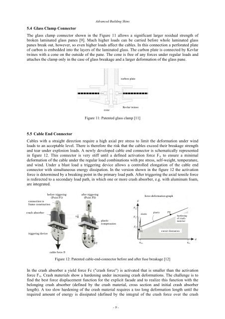
5.4 Glass C<strong>lamp</strong> Connector<br />
Advanced Building Skins<br />
The glass c<strong>lamp</strong> connector shown in the Figure 11 allows a significant larger residual strength of<br />
broken lamin<strong>at</strong>ed glass panes [9]. Much higher loads can be carried before whole lamin<strong>at</strong>ed glass<br />
panes break out, however, so even higher loads affect the cables. In this connection a perfor<strong>at</strong>ed pl<strong>at</strong>e<br />
of carbon is embedded into the layers of the lamin<strong>at</strong>ed glass. The carbon pl<strong>at</strong>e is connected by Kevlar<br />
twines with a cone on the outside of the pane. The cone is free of any forces under regular loads and<br />
<strong>at</strong>taches the c<strong>lamp</strong> only in the case of glass breakage and a larger deform<strong>at</strong>ion of the glass pane.<br />
Figure 11: P<strong>at</strong>ented glass c<strong>lamp</strong> [11]<br />
5.5 Cable End Connector<br />
Cables with a straight direction require a high axial pre stress to limit the deform<strong>at</strong>ion under wind<br />
loads to an acceptable level. There is therefore the risk th<strong>at</strong> the cables exceed their breakage strength<br />
and tear under explosion loads. A newly developed cable end connector is schem<strong>at</strong>ically represented<br />
in figure 12. This connector is very stiff until a defined activ<strong>at</strong>ion force FA to ensure a minimal<br />
deform<strong>at</strong>ion of the cable under the regular load combin<strong>at</strong>ions with pre stress, self-weight, temper<strong>at</strong>ure,<br />
and wind. Under a blast load a triggering device allows a controlled elong<strong>at</strong>ion of the cable end<br />
connector with simultaneous energy dissip<strong>at</strong>ion. In the version shown in the figure 12 the activ<strong>at</strong>ion<br />
force is determined by a breaking point in the primary load p<strong>at</strong>h. After triggering the axial tensile force<br />
is redirected to a secondary load p<strong>at</strong>h, in which one or more crash absorber, e.g. with aluminum foam,<br />
are integr<strong>at</strong>ed.<br />
before triggering<br />
(Point P1)<br />
connection to<br />
frame construction<br />
crash absorber<br />
triggering device<br />
cable force S<br />
after triggering<br />
(Point P2)<br />
cone<br />
plastic<br />
compression<br />
Figure 12: P<strong>at</strong>ented cable-end-connector before and after fuse breakage [12]<br />
In the crash absorber a yield force Fc ("crash force") is activ<strong>at</strong>ed th<strong>at</strong> is smaller than the activ<strong>at</strong>ion<br />
force FA. Crash m<strong>at</strong>erials show a hardening under increasing crash deform<strong>at</strong>ions. The challenge is to<br />
find the best force displacement function for the explicit facade and to realize this function with the<br />
belonging crash absorber (defined by the crash m<strong>at</strong>erial, cross section and initial crash absorber<br />
length). A too slow hardening of the crash m<strong>at</strong>erial requires a too long deform<strong>at</strong>ion length until the<br />
required amount of energy is dissip<strong>at</strong>ed (defined by the integral of the crash force over the crash<br />
- 9 -<br />
carbon pl<strong>at</strong>e<br />
Kevlar twines<br />
elastic<br />
force-deform<strong>at</strong>ion-graph<br />
plastic<br />
energy dissip<strong>at</strong>ion<br />
hardening<br />
of crash-<br />
m<strong>at</strong>erial