advanced building skins 14 | 15 June 2012 - lamp.tugraz.at - Graz ...
advanced building skins 14 | 15 June 2012 - lamp.tugraz.at - Graz ...
advanced building skins 14 | 15 June 2012 - lamp.tugraz.at - Graz ...

You also want an ePaper? Increase the reach of your titles
YUMPU automatically turns print PDFs into web optimized ePapers that Google loves.
Advanced Building Skins<br />
consultant are key factors in determining the success of a project. The process map shown in section 3<br />
indic<strong>at</strong>es th<strong>at</strong> this knowledge is not specific to a particular project and can be re-used. Therefore, the<br />
tool presented in this section has been developed to capture, store, use and re-use knowledge. The tool<br />
focuses on knowledge of the constraints manufacture imposes on the façade panelis<strong>at</strong>ion scheme.<br />
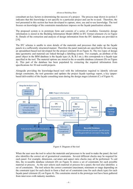
The proposed system is in prototype form and consists of a series of modules. Geometric design<br />
inform<strong>at</strong>ion is stored in the Building Inform<strong>at</strong>ion Model (BIM) in IFC form<strong>at</strong> (element (A) in Figure<br />
4). Details of the extraction and analysis of design inform<strong>at</strong>ion from the IFC d<strong>at</strong>abase are provided in<br />
[18].<br />
The IFC schema is unable to store details of the m<strong>at</strong>erials and processes th<strong>at</strong> make up the façade<br />
panels in a sufficiently structured manner. Therefore the panel m<strong>at</strong>erials are specified by the user using<br />
an spreadsheet-based tool developed for the project (element B on Figure 4). The two types of design<br />
d<strong>at</strong>a (geometric and m<strong>at</strong>erial) are linked through a labelling system. For example, an <strong>at</strong>tribute of the<br />
panel object in the BIM d<strong>at</strong>abase is the façade type (A, B, B.1 etc.); this corresponds to a façade type<br />
specified in the tool. The m<strong>at</strong>erial options are stored in the re-useable d<strong>at</strong>abase (element (D) on Figure<br />
4). This part of the d<strong>at</strong>abase has been popul<strong>at</strong>ed by extracting the required inform<strong>at</strong>ion from<br />
specific<strong>at</strong>ions for 30 real-world projects.<br />
Alongside providing the knowledge-based tool with the inform<strong>at</strong>ion required to identify relevant<br />
design constraints, the tool gener<strong>at</strong>es and upd<strong>at</strong>es the project façade typology report, a key (paperbased<br />
deliverable) of the façade consulting team during the design stages (element (C) of Figure 4).<br />
Figure 4: Diagram of the tool<br />
When the user uses the tool to select the m<strong>at</strong>erials and processes to be used to make the panel, the tool<br />
also identifies the correct set of geometrical constraints. Several different checks may be required for<br />
each panel. For example, dimension, curv<strong>at</strong>ure and aspect r<strong>at</strong>io checks may all be performed. To aid<br />
this, the re-useable d<strong>at</strong>abase (element (D) on Figure 4) stores a set of constraints for each possible<br />
m<strong>at</strong>erial or process. As the user selects each m<strong>at</strong>erial or process for a panel, the tool also identifies a<br />
set of constraints. The tool selects the correct constraint (maximum, minimum or range depending on<br />
the constraint type) for each check to form a final set of constraints (one for each check type) for each<br />
façade panel (element (E) on Figure 4). The constraints stored in the prototype tool have been g<strong>at</strong>hered<br />
from interviews with industry members.<br />
- 6 -