EN: man_8065_chn.pdf - Fagor Automation
EN: man_8065_chn.pdf - Fagor Automation
EN: man_8065_chn.pdf - Fagor Automation
Create successful ePaper yourself
Turn your PDF publications into a flip-book with our unique Google optimized e-Paper software.
Execution channels<br />
2.1.2 Distributing the channels and spindles between the different channels.<br />
Some of these parameters correspond to the common general parameters whereas others<br />
belong to the general parameters of each channel.<br />
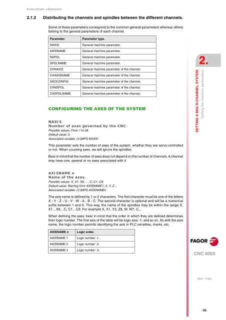
Parameter. Parameter type.<br />
NAXIS General machine parameter.<br />
AXISNAME General machine parameter.<br />
NSPDL General machine parameter.<br />
SPDLNAME General machine parameter.<br />
CHNAXIS General machine parameter of the channel.<br />
CHAXISNAME General machine parameter of the channel.<br />
GEOCONFIG General machine parameter of the channel.<br />
CHNSPDL General machine parameter of the channel.<br />
CHSPDLNAME General machine parameter of the channel.<br />
CONFIGURING THE AXES OF THE SYSTEM<br />
NAXIS<br />
Number of axes governed by the CNC.<br />
Possible values: From 1 to 28.<br />
Default value: 3.<br />
Associated variable: (V.)MPG.NAXIS<br />
This parameter sets the number of axes of the system, whether they are servo-controlled<br />
or not. When counting axes, we will ignore the spindles.<br />
Bear in mind that the number of axes does not depend on the number of channels. A channel<br />
may have one, several or no axes associated with it.<br />
AXISNAME n<br />
Name of the axes.<br />
Possible values: X, X1··X9, ·· , C, C1··C9.<br />
Default value: Starting from AXISNAME1; X, Y, Z...<br />
Associated variable: (V.)MPG.AXISNAMEn<br />
The axis name is defined by 1 or 2 characters. The first character must be one of the letters<br />
X - Y - Z - U - V - W - A - B - C. The second character is optional and will be a numerical<br />
suffix between 1 and 9. This way, the name of the spindles may be within the range X,<br />
X1…X9,...C, C1…C9. For example X, X1, Y3, Z9, W, W7, C...<br />
When defining the axes, bear in mind that the order in which they are defined determines<br />
their logic number. The first axis of the table will be logic axis -1- and so on. As with the axis<br />
name, the logic number permits identifying the axis in PLC variables, marks, etc.<br />
AXISNAME n Logic order.<br />
AXISNAME 1 Logic number ·1·.<br />
AXISNAME 2 Logic number ·2·.<br />
AXISNAME 3 Logic number ·3·.<br />
2.<br />
SETTING A MULTI-CHANNEL SYSTEM.<br />
Setting the machine parameters.<br />
CNC <strong>8065</strong><br />
(REF: 1103)<br />
·35·


