EN: man_8065_chn.pdf - Fagor Automation
EN: man_8065_chn.pdf - Fagor Automation
EN: man_8065_chn.pdf - Fagor Automation
Create successful ePaper yourself
Turn your PDF publications into a flip-book with our unique Google optimized e-Paper software.
Execution channels<br />
3.4 Consultation and modifiable signals associated with the –S–<br />
function.<br />
3.4.1 Consultation signals.<br />
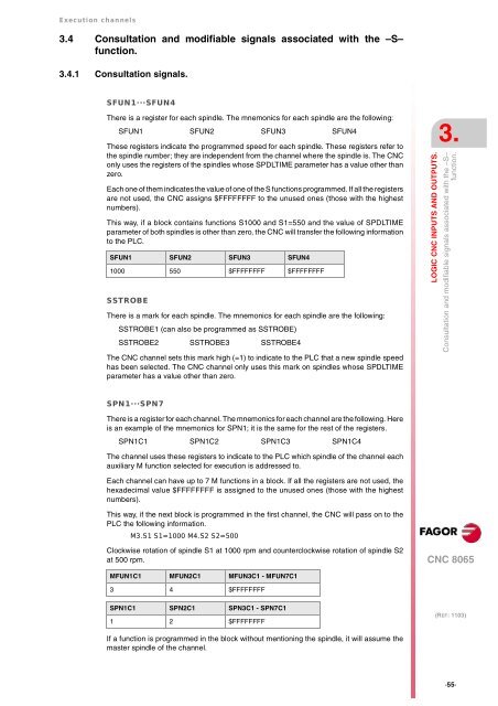
SFUN1···SFUN4<br />
There is a register for each spindle. The mnemonics for each spindle are the following:<br />
SFUN1 SFUN2 SFUN3 SFUN4<br />
These registers indicate the programmed speed for each spindle. These registers refer to<br />
the spindle number; they are independent from the channel where the spindle is. The CNC<br />
only uses the registers of the spindles whose SPDLTIME parameter has a value other than<br />
zero.<br />
Each one of them indicates the value of one of the S functions programmed. If all the registers<br />
are not used, the CNC assigns $FFFFFFFF to the unused ones (those with the highest<br />
numbers).<br />
This way, if a block contains functions S1000 and S1=550 and the value of SPDLTIME<br />
parameter of both spindles is other than zero, the CNC will transfer the following information<br />
to the PLC.<br />
SFUN1 SFUN2 SFUN3 SFUN4<br />
1000 550 $FFFFFFFF $FFFFFFFF<br />
SSTROBE<br />
There is a mark for each spindle. The mnemonics for each spindle are the following:<br />
SSTROBE1 (can also be programmed as SSTROBE)<br />
SSTROBE2 SSTROBE3 SSTROBE4<br />
The CNC channel sets this mark high (=1) to indicate to the PLC that a new spindle speed<br />
has been selected. The CNC channel only uses this mark on spindles whose SPDLTIME<br />
parameter has a value other than zero.<br />
SPN1···SPN7<br />
There is a register for each channel. The mnemonics for each channel are the following. Here<br />
is an example of the mnemonics for SPN1; it is the same for the rest of the registers.<br />
SPN1C1 SPN1C2 SPN1C3 SPN1C4<br />
The channel uses these registers to indicate to the PLC which spindle of the channel each<br />
auxiliary M function selected for execution is addressed to.<br />
Each channel can have up to 7 M functions in a block. If all the registers are not used, the<br />
hexadecimal value $FFFFFFFF is assigned to the unused ones (those with the highest<br />
numbers).<br />
This way, if the next block is programmed in the first channel, the CNC will pass on to the<br />
PLC the following information.<br />
M3.S1 S1=1000 M4.S2 S2=500<br />
Clockwise rotation of spindle S1 at 1000 rpm and counterclockwise rotation of spindle S2<br />
at 500 rpm.<br />
MFUN1C1 MFUN2C1 MFUN3C1 - MFUN7C1<br />
3 4 $FFFFFFFF<br />
SPN1C1 SPN2C1 SPN3C1 - SPN7C1<br />
1 2 $FFFFFFFF<br />
If a function is programmed in the block without mentioning the spindle, it will assume the<br />
master spindle of the channel.<br />
3.<br />
LOGIC CNC INPUTS AND OUTPUTS.<br />
Consultation and modifiable signals associated with the –S–<br />
function.<br />
CNC <strong>8065</strong><br />
(REF: 1103)<br />
·55·


