

1928 Cadillac - GM Heritage Center
1928 Cadillac - GM Heritage Center
1928 Cadillac - GM Heritage Center

Create successful ePaper yourself
Turn your PDF publications into a flip-book with our unique Google optimized e-Paper software.
CADILLAC OPERATOR'S MANUAL<br />
EQUIPMENT j 9 2 S C/1D/AMC<br />
33<br />
On cars driven at high speeds, the front tires should be inflated to 50 lbs.<br />
This is important.<br />
Tire Air Compressor<br />
To use the tire air compressor with which the car is equipped, proceed<br />
as follows:<br />
Turn back the left-hand side of the front carpet and lift the small ovalshaped<br />
cover which is in the floor, just to the left of the transmission control<br />
lever. Reach through the hole in the floor and remove the knurled<br />
cap from the connection on top of the compressor. Connect one end of the<br />
air hose (in the tool equipment) to this connection and at the other end<br />
of the hose to the valve of the tire to be inflated. Do not connect the hose<br />
to the tire first, if there is pressure in the tire.<br />
The control shaft, by which the compressor driving gear is placed in<br />
mesh with the transmission gears, projects through a small hole in the<br />
floor, just in front of the large hole over the compressor. To start the compressor,<br />
if the engine is running, disengage the clutch and hold the pedal<br />
down until the transmission gears have ceased to revolve. Then, with a<br />
screw-driver, turn the slotted head of the compressor control shaft clockwise.<br />
If the engine is not running, simply turn the control shaft clockwise,<br />
without disengaging the clutch and then start the engine.<br />
The compressor gives best results when the engine runs at a speed of<br />
approximately 1000 r.p.m., which is about three times the normal speed<br />
of the engine when idling. Do not race the engine in operating the compressor,<br />
or, for that matter, at any other time when it is not driving the<br />
car. Racing the engine beyond the<br />
recommended speed not only decreases<br />
the efficiency of the compressor,<br />
but is one of the worst<br />
forms of abuse. To stop the compressor,<br />
turn the control shaft counter-clockwise.<br />
Do not turn the compressor control<br />
shaft to start the compressor<br />
when the engine is running and the<br />
clutch is engaged.<br />
rim has on it three lugs, which are located so as to engage with notches<br />
on the support arms and on the adjustable clamps. There are two sets of<br />
these notches in the support arms.<br />
When two rims are carried, the rim nearest the car should be placed so<br />
that the side with the lugs is away from the car, and the lugs should be<br />
inserted in the inner set of notches. The outer rim should then be placed<br />
so that the side with the lugs faces toward the car and the lugs of this rim<br />
should be inserted in the outer set of notches.<br />
When onlv one rim is carried, the side of the rim with the lugs should<br />
lace awav from the car, and the lugs should be inserted in the outer set<br />
of notches. This permits the rim to be clamped by the outer clamp.<br />
The lock is' in the upper end of the outer clamp screw and is protected<br />
hv a dust cap, which must be unscrewed to insert the key. Turning the key<br />
clockwise disengages the lock, permitting the clamp screw to be turned.<br />
To lock the outer clamp, screw the clamp down firmly against the rim<br />
or rims. Adjust the clamp screw handle so that it points squarelv across<br />
the car. Then turn the key counter-clockwise. Care should be exercised<br />
in removing or replacing a spare tire not to strike the body of the car.<br />
NOTE: If a wrap-around type tire cover is used, it should have slots<br />
cut in it opposite the two upper lugs on the rim, so as to permit these<br />
lugs to seat in the notches in the support arms.<br />
Wire Wheel Carrier<br />
To remove the spare wire wheel from the carrier, first unscrew the dust<br />
cap which protects the lock. Insert the key in the lock and turn it to the<br />
Tire Carrier<br />
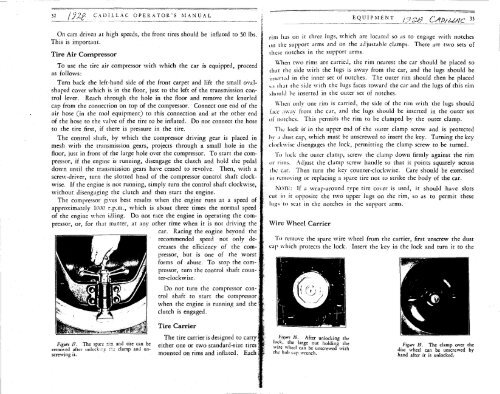
The tire carrier is designed to carry<br />
Figun 17. The spare rini and tire can be ei tne r one or two standard-size tires<br />
removed after unlockine ;r.e clamp and un- . . . ,<br />
screwing it. ' mounted on rims and inflated, .bach<br />
I


