- Page 1 and 2:
f CADILLAC MOTOR CAR COMPANY & I \
- Page 3 and 4:
I THE X E W (' A DILL A C 9 etaiL o
- Page 5 and 6:
THE NEW CADILLAC A SURPASSING POWER
- Page 7 and 8:
TIIK NEW CADILLAC KIGIDITY OF CHANK
- Page 9 and 10:
T1IK NEW CADILLAC DETAILS OF OOXHT1
- Page 11 and 12:
THE NEW CADILLAC DETAILS OK COXSTHC
- Page 13 and 14:
THE XKW CADILLAC arranged in an ind
- Page 15 and 16:
THE N li W (.UHLLAC e ull floating
- Page 17 and 18:
KKI'AII.S OK COXSTK (CTION PART CAD
- Page 19 and 20:
THK XKW CADILLAC ie long wheelba.se
- Page 21 and 22:
DETAILS III' COXSTUI'CTION Wider, d
- Page 23 and 24:
THE NEW CADILLAC out" under the rea
- Page 25 and 26: THE NEW CADILLAC in. narrow rim wit
- Page 27 and 28: Copyright 1*>2S bv adiliac Motor Ca
- Page 29 and 30: CHAPTER V—Care of Tires 63 Inflat
- Page 31 and 32: 10 CADILLAC OPERATORS MANUAL OPERAT
- Page 33 and 34: 14 CADILLAC OPERATOR'S MANUAL OPERA
- Page 35 and 36: 18 CADILLAC OPERATOR'S MANUAL OPERA
- Page 37 and 38: 22 CADILLAC OPERATOR'S MANUAL OPERA
- Page 39 and 40: 26 CADILLAC OPERATOR'S MANUAL OPERA
- Page 41 and 42: 30 CADILLAC OPERATOR'S MANUAL The T
- Page 43 and 44: 34 CADILLAC OPERATOR'S MANUAL Infla
- Page 45 and 46: 38 CADILLAC OPERATOR'S MANUAL OPERA
- Page 47 and 48: 42 CADILLAC OPERATOR'S MANUAL OPERA
- Page 49 and 50: PART II LUBRICATION AND CARE
- Page 51 and 52: 50 CADILLAC OPERATOR'S MANUAL LUBRI
- Page 53 and 54: 54 CADILLAC OPERATOR'S MANUAL LUBRI
- Page 55 and 56: LUBRICATION AND CARE 59 Wheels; 1,
- Page 57 and 58: 62 CADILLAC OPERATOR'S MANUAL Do no
- Page 59 and 60: CHAPTER VI Storing Car IF THE car i
- Page 61 and 62: GENERAL INFORMATION 71 CHAPTER I En
- Page 63 and 64: 74 CADILLAC OPERATOR'S MANUAL GENER
- Page 65 and 66: GENERAL INFORMATION 79 Water Circul
- Page 67 and 68: GENERAL INFORMATION 83 u .">o I*. T
- Page 69 and 70: 86 CADILLAC OPERATOR'S MANUAL it ca
- Page 71 and 72: 90 CADILLAC OPERATOR'S MANUAL the c
- Page 73 and 74: 94 CADILLAC OPERATOR'S MANUAL (Fig.
- Page 75: Description CHAPTER VI Steering Gea
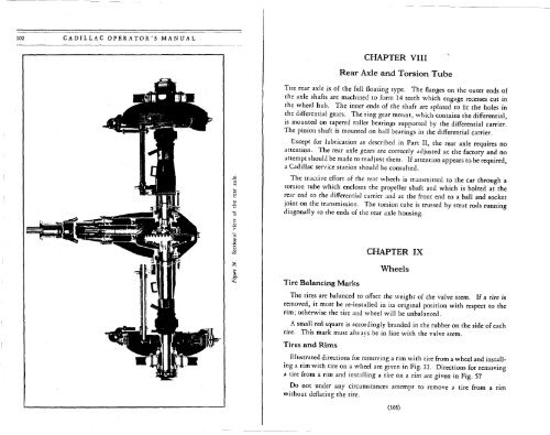
- Page 79 and 80: 106 CADILLAC OPERATOR'S MANUAL GENE
- Page 81 and 82: lid CADILLAC OPERATOR'S MANUAL GENE
- Page 83 and 84: GENERAL INFORM ATION 115 Type of en
- Page 85 and 86: 118 CADILLAC OPERATOR'S MANUAL Solu
- Page 87 and 88: CADILLAC Operator's Manual CADILLAC
- Page 89 and 90: CHAPTER I Cadillac Service THE owne
- Page 91 and 92: CADILLAC OPERATOR'S MANUAL best pos
- Page 93 and 94: 12 CADILLAC OPERATOR'S MANUAL OPERA
- Page 95 and 96: 16 CADILLAC OPERATOR'S MANUAL OPERA
- Page 97 and 98: 20 CADILLAC OPERATOR'S MANUAL Speed
- Page 99 and 100: 24 CADILLAC OPERATOR'S MANUAL EQUIP
- Page 101 and 102: 28 CADILLAC OPERATOR'S MANUAL EQUIP
- Page 103 and 104: CADILLAC OPERATOR'S MANUAL EQUIPMEN
- Page 105 and 106: 36 CADILLAC OPERATOR'S MANUAL EQUIP
- Page 107 and 108: V | HfScS OWNE -R'^ ADDR F-crc ENGH
- Page 109 and 110: LUBRICATION 45 44 CADILLAC OPERATOR
- Page 111 and 112: 48 CADILLAC OPERATOR'S MANUAL Winte
- Page 113 and 114: 52 CADILLAC OPERATOR'S MANUAL GENER
- Page 115 and 116: STORING CAR 57 CHAPTER VII Storing
- Page 117 and 118: 60 CADILLAC OPERATOR'S MANUAL porta
- Page 119 and 120: .19?fl Shop Manual Cad'llac 3^1-.^3
- Page 121 and 122: Foreword HPHIS Shop Manual is a boo
- Page 123 and 124: 4 CONTENTS Engine Specifications 63
- Page 125 and 126: Front Axle Subject Cadillac 341 LaS
- Page 127 and 128:
FRONT AXLE 9 Punch 1/8-inch hole in
- Page 129 and 130:
FRONT AXLE 11 r~\ Front —A— f~\
- Page 131 and 132:
Rear Axle and Torsion Tube Subject
- Page 133 and 134:
REAR AXLE AND TORSION TUBE 15 Drive
- Page 135 and 136:
REAR AXLE AND TORSION TUBE 17 To di
- Page 137 and 138:
Note: Adjustment of connections,whe
- Page 139 and 140:
Note: Adjustment of connections, wh
- Page 141 and 142:
24 BRAKES Note: Unless brake connec
- Page 143 and 144:
Note: Adjustment of connections mus
- Page 145 and 146:
Note: Adjustment of connections mus
- Page 147 and 148:
30 BRAKES Note: Unless brake connec
- Page 149 and 150:
32 BRAKES Note: Unless brake connec
- Page 151 and 152:
Clutch Subject Cadillac 341 1-aSall
- Page 153 and 154:
CLUTCH 37 Rear driving plate Center
- Page 155 and 156:
CLUTCH 39 Rod to clutch pedal Ball
- Page 157 and 158:
42 COOLING SYSTEM Filler Assemble w
- Page 159 and 160:
44 COOLING SYSTEM 4. Flushing Cooli
- Page 161 and 162:
Electrical System Subject Cadillac
- Page 163 and 164:
ELECTRICAL SYSTEM 49 Subject Cadill
- Page 165 and 166:
ELECTRICAL SYSTEM 51 Subject Cadill
- Page 167 and 168:
ELECTRICAL 53 Fig.l Top view with h
- Page 169 and 170:
ELECTRICAL 55 Fig. 2 Electrolock fr
- Page 171 and 172:
CIRCUIT BREAKER INSTRUMENT PANEL LA
- Page 173 and 174:
CUT-OUT RELAY CIRCUIT BREAKERS LOCK
- Page 175 and 176:
A-T#JL-6-B-3CP8ULB B-5TOP-6-8-2ICP.
- Page 177 and 178:
Intake header shield (not used on L
- Page 179 and 180:
66 ENGINE To remove chain, remove c
- Page 181 and 182:
68 ENGINE Fig. 1 Numbering of conne
- Page 183 and 184:
70 ENGINE Use new wood plugs when r
- Page 185 and 186:
72 ENGINE dicated with a dial indic
- Page 187 and 188:
ENGINE 100-600 pounds press fit Pis
- Page 189 and 190:
76 FRAME Plate 41. Diagrams of Cadi
- Page 191 and 192:
78 GASOLINE SYSTEM Automatic thrott
- Page 193 and 194:
80 GASOLINE SYSTEM Fig. 1 Cadillac
- Page 195 and 196:
82 LIGHTING SYSTEM One-half of dist
- Page 197 and 198:
IS p l-h n •*» 0\ r ^- o rt- **
- Page 199 and 200:
Each "G" indicates a grease-gun con
- Page 201 and 202:
Springs Subject Cadillac 341 LaSall
- Page 203 and 204:
Subject Cadillac 341 Steering Gear
- Page 205 and 206:
STEERING GEAR 93 Clamp bolt Turn nu
- Page 207 and 208:
High and intermediate sliding coupl
- Page 209 and 210:
98 TRANSMISSION AND UNIVERSAL JOINT
- Page 211 and 212:
Sliding coupling with external teet
- Page 213 and 214:
2 re
- Page 215 and 216:
Shifter forks Shifter shaft and int
- Page 217 and 218:
Wheels, Rims and Tires Subject Cadi
- Page 219 and 220:
( i tJ^, a (.,(,1,11,1¼ BO.l •ft
- Page 221 and 222:
Contents DM 01 - 6 c P p^ NOTE: The
- Page 223 and 224:
Introduction 0Q*° ! Arrangements o
- Page 225 and 226:
Sf f\ £> ^ FRONT AXLE **J (¾ Subj
- Page 227 and 228:
10 FRONT AXLE Adjustable lever Knuc
- Page 229 and 230:
12 FRONT AXLE m^ e- -e- 1/32 inch I
- Page 231 and 232:
14 REAR AXLE AND TORSION TUBE 1. Lu
- Page 233 and 234:
16 REAR AXLE AND TORSION TUBE Drive
- Page 235 and 236:
c c Subject FOOT BRAKES Front and R
- Page 237 and 238:
BRAKES 21 Subject Cadillac 341 LaSe
- Page 239 and 240:
BRAKES 23 Note: [links Unless brake
- Page 241 and 242:
BRAKES 25 Lever on rocker shaft Cen
- Page 243 and 244:
.^ ,., i—- m m Equalizer ba 5 Adj
- Page 245 and 246:
.""> Use upper hole for 14-inch fro
- Page 247 and 248:
BRAKES 31 Note: Unless brake connec
- Page 249 and 250:
BRAKES 33 Note: Unless brake connec
- Page 251 and 252:
36 CLUTCH Subject Cadillac 341 LaSa
- Page 253 and 254:
38 CLUTCH /Test by hand, not by foo
- Page 255 and 256:
Cooling System Subject Cadillac 341
- Page 257 and 258:
COOLING SYSTEM 43 Subject Cadillac
- Page 259 and 260:
COOLING SYSTEM 45 Fig. 2 Enlarged h
- Page 261 and 262:
48 ELECTRICAL Fig. 1 Sectional view
- Page 263 and 264:
50 ELECTRICAL Spring adjusting scre
- Page 265 and 266:
52 ELECTRICAL SYSTEM 5. Adding Wate
- Page 267 and 268:
54 ELECTRICAL Tool I0i Fig. 1 Testi
- Page 269 and 270:
Adjustment of starter switch. 1 Scr
- Page 271 and 272:
oo A-TML-64-3 CP BULB B-STOH-M-SIC*
- Page 273 and 274:
s A-Wi.-«-s-sc.PNx» B-noP-64-ncit
- Page 275 and 276:
Engine Subject Cadillac 341 LaSalle
- Page 277 and 278:
ENGINE 65 Subject Cadillac 341 LaSa
- Page 279 and 280:
ENGINE 67 Subject Cadillac 341 USal
- Page 281 and 282:
ENGINE 69 Subject Cadillac 341 USal
- Page 283 and 284:
c Subject INLET VALVES Clearance be
- Page 285 and 286:
C) ENGINE 73 By-pass adjusting scre
- Page 287 and 288:
Frame Subject Cadillac 341 LaSalle
- Page 289 and 290:
Gasoline System Subject Cadillac 34
- Page 291 and 292:
LaSalle inlet connection and strain
- Page 293 and 294:
Lighting System Subject Cadillac 34
- Page 295 and 296:
( Lubrication Subject Cadillac 341
- Page 297 and 298:
\ rs ^ Rear shackles Brake shafts u
- Page 299 and 300:
\ ^N Each "G" indicates a grease-gu
- Page 301 and 302:
90 SPRINGS AND SHOCK ABSORBERS -Bol
- Page 303 and 304:
90B SPRINGS AND SHOCK ABSORBERS Sub
- Page 305 and 306:
92 STEERING GEAR First-type screw.
- Page 307 and 308:
94 STEERING GEAR Steering gear arm
- Page 309 and 310:
High and intermediate sliding coupl
- Page 311 and 312:
98 TRANSMISSION AND UNIVERSAL JOINT
- Page 313 and 314:
98-B TRANSMISSION AND UNIVERSAL JOI
- Page 315 and 316:
8 H yo > z Cfl *•« Cfl Cfl e-i O
- Page 317 and 318:
pq Drum engaged B with cone and syn
- Page 319 and 320:
Shifter forks Shifter shaft igh and
- Page 321 and 322:
Wheels, Rims and Tires Subject Cadi