

1928 Cadillac - GM Heritage Center
1928 Cadillac - GM Heritage Center
1928 Cadillac - GM Heritage Center

You also want an ePaper? Increase the reach of your titles
YUMPU automatically turns print PDFs into web optimized ePapers that Google loves.
Description<br />
CHAPTER VI<br />
Steering Gear<br />
THE <strong>Cadillac</strong> steering gear is of the worm and sector type. In this construction,<br />
the tube or shaft, to which the steering wheel is fastened, has on<br />
its lower end a worm which engages a sector gear. The steering arm is<br />
fastened to the shaft of this sector gear.<br />
The steering gear has three adjustments: one to adjust the position of the<br />
sector in its relation to the worm; a second to take up end-play in the worm<br />
thrust bearings; and a third to take up end-play in the sector shaft.<br />
Adjustment of Worm and Sector<br />
This adjustment consists in moving the sector away from or toward the<br />
worm, so as to give the proper amount of backlash. Provision is made for<br />
doing this by means of the sleeve or bushing in which the sector shaft turns.<br />
The outside of this bushing is eccentric, and by turning the hexagonal end<br />
of the bushing, which projects through the side bar of the frame, the sector<br />
can be moved away from or toward the worm. To make the adjustment,<br />
proceed as follows:<br />
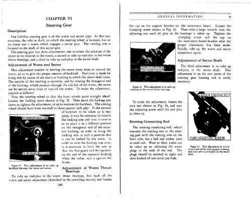
Turn the steering wheel so that the front wheels point straight ahead.<br />
Loosen the locking screw shown in Fig. 51- Then move the locking arm<br />
down to tighten the adjustment, or up to increase the backlash. The steering<br />
wheel should have from one-half to three-quarter inch play. If the amount<br />
of backlash to be taken up is very<br />
great, it may be necessary to remove<br />
the locking arm and turn it over so<br />
as to place it in a different position<br />
on the hexagonal end of the eccentric<br />
bushing, in order to bring the<br />
locking arm in such a position that<br />
it can be locked by the screw. In<br />
order to turn the locking arm over,<br />
it is necessary to bend the arm so<br />
that the hexagonal end fits squarely<br />
on the end of the eccentric bushing<br />
when the other end is against the<br />
frame.<br />
Figure 51. This adjustment is to take up<br />
backlash between the worm and sector. Adjustment of Worm Thrust<br />
Bearings<br />
To take up end-play in the worm thrust bearings, first back off the<br />
worm and sector adjustment (described in the preceding section) and loosen<br />
(98)<br />
GENERAL INFORMATION 99<br />
the cap on the support bracket on the instrument board. Loosen the<br />
clamping screw shown in Fig. 52. Then with a large wrench turn the<br />
adjusting nut until all play in the bearings is taken up. Tighten the<br />
clamping screw and the cap on<br />
the instrument board bracket after the<br />
proper adjustment has been made.<br />
Finally, take up the worm and sector<br />
adjustment again.<br />
Figure 51. This adjustment is to take up<br />
end-play in the worm thrust bearings.<br />
To make the adjustment, loosen the<br />
lock nut shown in Fig. 53, and turn<br />
the adjusting screw until the end play<br />
is taken up.<br />
Steering Connecting Rod<br />
The steering connecting rod, which<br />
connects the steering arm at the steering<br />
gear with the steering arm on the<br />
front axle, has a ball and socket joint<br />
at each end. Wear at these joints can<br />
be taken up by adjusting the screw<br />
plugs in the ends of the rod. The<br />
plugs should be screwed in tight and<br />
then backed off one cotter pin hole.<br />
Adjustment of Sector Shaft<br />
The third adjustment is to take up<br />
end-play in the sector shaft. This<br />
adjustment is on the rear cover of the<br />
steering gear housing and is rarely<br />
necessary.<br />
SEN LOCKING NUT<br />
Figure 53. This adjustment is on the<br />
cover plate of the steering gear housing,<br />
and is to take up end play in the sector<br />
shaft.


