

1928 Cadillac - GM Heritage Center
1928 Cadillac - GM Heritage Center
1928 Cadillac - GM Heritage Center

Create successful ePaper yourself
Turn your PDF publications into a flip-book with our unique Google optimized e-Paper software.
94 CADILLAC OPERATOR'S MANUAL<br />
(Fig. 47a.) Tighten the nut securely,<br />
taking care not to move the lamp out<br />
of adjustment.<br />
No adjustment for the lower beam is<br />
necessary. If the lamp has been correctly<br />
focused and aimed with the upper<br />
beam on, the lower beam will appear<br />
as in Fig 47b.<br />
If it is desired to focus the lamp<br />
with the door removed, this can be<br />
done. Fig. 47c shows the upper beam<br />
as it should appear with the lens removed.<br />
figure 48. Headlamp adjusting screw.<br />
CHAPTER V<br />
Clutch and Transmission<br />
Clutch<br />
The <strong>Cadillac</strong> clutch is a disc clutch of exclusive design. There are three<br />
driving plates, the center plate being bolted to the flywheel. The front<br />
and rear driving plates float or slide on pins carried by the center plate.<br />
There are two driven discs, one between the center and rear driving plates<br />
and the other between the center and front driving plates. Both discs are<br />
bolted to a central hub which slides on the splined end of the clutch shaft. The<br />
discs are wheel shaped, lined on both sides with a ring of friction material.<br />
When the clutch is engaged, the plates and discs are pressed firmly together<br />
under the pressure of twelve 70-lb. springs. The driven discs then<br />
revolve with the flywheel, and the engine, if running, drives the transmission.<br />
When the clutch pedal is pushed down to disengage the clutch, a series<br />
of levers releases the pressure of the springs and the driven discs separate<br />
from the driving plates, permitting the flywheel to revolve independently<br />
of the transmission.<br />
The clutch itself requires no adjustment or attention other than lubrication<br />
of the clutch thrust bearing, as directed on page 57. Adjustment of the<br />
clutch release rod, however, may be necessary after the car has been driven<br />
some distance.<br />
Adjustment of Clutch Release Rod<br />
As described on page 16, the clutch pedal is purposely given about one<br />
inch of "lost motion." That is, the clutch does not begin to disengage until<br />
the pedal has been moved down about an inch from its released position.<br />
This lost motion is necessary in order<br />
to allow the clutch discs to come<br />
closer together as the facings are<br />
reduced in thickness. The lost<br />
motion gradually decreases as the<br />
clutch is used, and eventually will<br />
be taken up. Before this happens,<br />
the clutch release rod must be readjusted<br />
to restore the lost motion;<br />
otherwise the clutch discs will slip<br />
and the engine will not drive the car.<br />
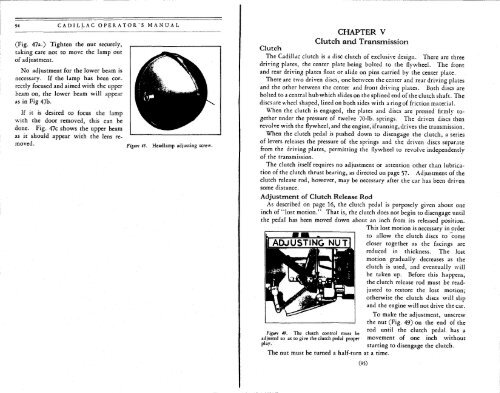
To make the adjustment, unscrew<br />
the nut (Fig. 49) on the end of the<br />
r .„ T, , • , , rod until the clutch pedal has a<br />
Figure 49. The clutch control must be . .<br />
adjusted so as to give the clutch pedal proper movement of one inch without<br />
P •'<br />
starting to disengage the clutch.<br />
The nut must be turned a half-turn at a time.<br />
(95)


