

1928 Cadillac - GM Heritage Center
1928 Cadillac - GM Heritage Center
1928 Cadillac - GM Heritage Center

You also want an ePaper? Increase the reach of your titles
YUMPU automatically turns print PDFs into web optimized ePapers that Google loves.
34 CADILLAC OPERATOR'S MANUAL<br />
Inflation Pressure<br />
For normal driving, the 32 by 6.75 low pressure tires, which are<br />
standard equipment on <strong>Cadillac</strong> cars, thould be inflated to a pressure of<br />
40 lbs. per square inch. The inflation pressure should be checked at<br />
least weekly and should not be permitted to drop more than 5 lbs.<br />
On cars driven at high speeds, the front tires should be inflated to 50 lbs.<br />
or higher if necessary. This is important.<br />
Tire Air Compressor<br />
To use the tire air compressor with which the car is equipped, proceed as<br />
follows:<br />
Turn back the left-hand side of the front carpet and lift the small ovalshaped<br />
cover which is in the floor just to the left of the transmission control<br />
lever. Reach through the hole in the floor and remove the knurled cap from<br />
the connection on top of the compressor. Connect one end of the air hose<br />
(in the tool equipment) to this connection and the other end of the hose to<br />
the valve of the tire to be inflated. Do not connect the bose to the tire first if<br />
there is pressure in the tire.<br />
The control shaft by which the compressor driving gear is placed in mesh<br />
with the transmission gears projects through a small hole in the floor just in<br />
front of the large hole over the compressor. To start the compressor, if<br />
the engine is running, disengage the clutch and hold the pedal down until<br />
the transmission gears have ceased to revolve. Then, with a screw-driver,<br />
turn the slotted head of the compressor control shaft clockwise. If the engine<br />
is not running, simply turn the control shaft clockwise without disengaging<br />
the clutch and then start the engine.<br />
The compressor gives best results when the engine runs at a speed of<br />
approximately 1000 r. p. m., which is about three times the normal speed of<br />
the engine when idling. Do not race the engine in operating the compressor,<br />
or, for that matter, at any other time when it is not driving the car.<br />
Racing the engine beyond the recommended speed not only decreases the<br />
efficiency of the compressor, but is one of the worst forms of abuse. To stop<br />
the compressor, turn the control shaft counter-clockwise.<br />
Do not turn the compressor control shaft to start the compressor when the<br />
engine is running and the clutch is engaged.<br />
Tire Holder<br />
The tire holder is designed to carry either one or two standard-size tires<br />
mounted on rims and inflated. Each rim has on it three lugs which are<br />
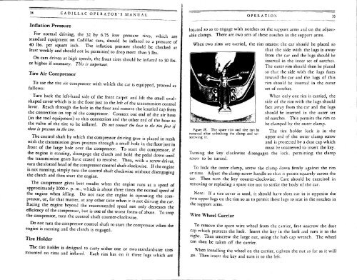
Figure IS. The spare rim and tire can be<br />
removed after unlocking the clamp and unscrewing<br />
it.<br />
OPERATION 35<br />
located so as to engage with notches on the support arms and on the adjustable<br />
clamps. There are two sets of these notches in the support arms.<br />
When two rims are carried, the rim nearest the car should be placed so<br />
that the side with the lugs is away<br />
from the car and the lugs should be<br />
inserted in the inner set of notches.<br />
The outer rim should then be placed<br />
so that the side with the lugs faces<br />
toward the car and the lugs of this<br />
rim should be inserted in the outer<br />
set of notches.<br />
When only one rim is carried, the<br />
side of the rim with the lugs should<br />
face away from the car and the lugs<br />
should be inserted in the outer set<br />
of notches. This permits the rim to<br />
be clamped by the outer clamp.<br />
The tire holder lock is in the<br />
upper end of the outer clamp screw<br />
and is protected by a dust cap which<br />
must be unscrewed to insert the key.<br />
Turning the key clockwise disengages the lock, permitting the clamp<br />
screw to be turned.<br />
To lock the outer clamp, screw the clamp down firmly against the rim<br />
or rims. Adjust the clamp screw handle so that it points squarely across the<br />
car. Then turn the key counter-clockwise. Care should be exercised in<br />
removing or replacing a spare tire not to strike the body of the car.<br />
Note: If a tire cover is used, it should have slots cut in it opposite the<br />
two upper lugs on the rim so as to permit these lugs to seat in the notches in<br />
the support arms.<br />
Wire Wheel Carrier<br />
To remove the spare wire wheel from the carrier, first unscrew the dust<br />
cap which protects the lock. Insert the key in the lock and turn it to the<br />
nght. Then unscrew the large nut, using the hub cap wrench. The wheel<br />
can then be taken off the carrier.<br />
When installing the wheel on the carrier, tighten the nut as far as it will<br />
£0. Then insert the kev and turn it to the left.


