

1928 Cadillac - GM Heritage Center
1928 Cadillac - GM Heritage Center
1928 Cadillac - GM Heritage Center

Create successful ePaper yourself
Turn your PDF publications into a flip-book with our unique Google optimized e-Paper software.
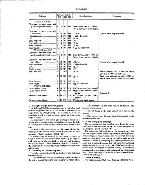
ENGINE 71<br />
Subject<br />
<strong>Cadillac</strong><br />
341<br />
LaSallc<br />
303-328<br />
Specifications<br />
Remarks<br />
INLET VALVES<br />
Clearance between stern and<br />
guide in cylinder blocks...<br />
Clearance between stem and<br />
valve lifter<br />
Head diameter<br />
Lift<br />
Seat, angle of<br />
Seat, width of<br />
Stem diameter<br />
Stem length<br />
EXHAUST VALVES<br />
Clearance between stem and<br />
guide in cylinder block<br />
Clearance between stem and<br />
valve lifter<br />
Head diameter ,<br />
Lift<br />
Angle of seat<br />
Seat, width of<br />
Stem diameter<br />
Stem length<br />
VALVE TIMING<br />
Intake valve, opens<br />
Intake valve, closes<br />
Exhaust valve, opens.<br />
Exhaust valve, closes.<br />
A<br />
A<br />
A<br />
A<br />
A»<br />
A«<br />
A<br />
A<br />
A<br />
A<br />
A<br />
A<br />
B<br />
B<br />
303<br />
303<br />
303<br />
303<br />
303<br />
303<br />
303<br />
303<br />
303<br />
303 328<br />
303 328<br />
303 328<br />
303 328<br />
3031<br />
303<br />
303<br />
303<br />
303<br />
303<br />
303<br />
303<br />
328<br />
328<br />
328<br />
328<br />
328<br />
328<br />
328<br />
328<br />
328<br />
328<br />
328<br />
328<br />
328<br />
328<br />
328<br />
328<br />
New limits, .001 to .003 5 in.<br />
Worn limit, not over .006 in.<br />
.004 in.<br />
1.660—1.666 in.<br />
tfin.<br />
30°<br />
A in.<br />
Viin.<br />
6 ft in from seat<br />
New limits, .002 to .0045 in<br />
Worn limit, not over .006 in.<br />
.006 in.<br />
1.634—1.640 in.<br />
Hin.<br />
45°<br />
A in.<br />
A in.<br />
%\n.<br />
t>yb in. from seat<br />
9½° before top dead center"<br />
58½° after bottom dead<br />
center<br />
46° before bottom dead<br />
center<br />
5° after top dead center<br />
Adjust when engine is cold.<br />
Adjust when engine is cold.<br />
Before engine unit 3-5809 on 341-A<br />
cars and 2-15992 on 303 cars.<br />
Beginning with engine unit 3-5809 on<br />
341-A cars and 2-15992 on 303 cars.<br />
See note 8.<br />
1. Straightening Connecting Rods<br />
La Salle and <strong>Cadillac</strong> connecting rods are of alloy steel<br />
of such toughness that it is not entirely satisfactory to<br />
align them by straightening. If attempt is made to<br />
straighten a rod it is apt to return sooner or later to its<br />
original shape.<br />
In manufacture, the piston pin bushing is bored in a<br />
fixture which insures perfect parallelism between the hole<br />
in the large end of the rod and the hole bored in the bushing.<br />
In service, the same thing can be accomplished by<br />
reaming on the special fixture which is provided for this<br />
purpose. (Tool Numbers 109214-5-6).<br />
If straightening is resorted to, care must be taken to<br />
bend or twist the rod farther than necessary to align it<br />
and then spring the rod back in the original direction<br />
until it is straight. This procedure helps to "normalize"<br />
the strains in the steel and prevent further distortion from<br />
taking place.<br />
2. Assembly of Connecting Rods<br />
The following points should be checked when installing<br />
connecting rods:<br />
I. The chamfered face of the bearings should be toward<br />
the end of the crankpin, the plain faces toward each other.<br />
2. The numbers on the rods should be toward the<br />
bottom of the engine.<br />
3. The oil holes in the rods should point toward the<br />
pistons.<br />
4. The numbers on the caps should correspond to the<br />
numbers on the rods.<br />
3. Connecting Rod Bearings<br />
The connecting-rod bearing clearance should be measured<br />
with a dial indicator using the fixture designed for<br />
the purpose. (Tool Number 109414).<br />
The connecting rod bearings are not separate parts but<br />
are cast in place in the connecting rod by a special process.<br />
The bearings are not adjustable and no attempt should be<br />
made to dress down the cap on the rod to take up the<br />
clearance. When a connecting rod bearing clearance exceeds<br />
the prescribed amount the rod should be removed<br />
and replaced with a rebabbitted rod. Rebabbitting of rods<br />
should not be attempted outside the factory. Rods should<br />
be returned to the factory and exchanged for rebabbitted<br />
rods. Rods, the caps of which have been dressed down,<br />
will not be exchanged.<br />
4. Main Bearings<br />
It is recommended that main bearing clearance be in-


