

1928 Cadillac - GM Heritage Center
1928 Cadillac - GM Heritage Center
1928 Cadillac - GM Heritage Center

You also want an ePaper? Increase the reach of your titles
YUMPU automatically turns print PDFs into web optimized ePapers that Google loves.
GENERAL INFORMATION 109<br />
General Description<br />
CHAPTER X<br />
Brakes<br />
THERE are three pairs of brakes: The rear wheel external brakes, the rear<br />
wheel internal brakes, and the front wheel brakes, which are also internal.<br />
The rear wheel external brakes and the front wheel brakes are operated by<br />
the brake pedal and comprise the foot brakes. The rear wheel internal brakes<br />
are operated by the hand lever and are used principally for locking the<br />
rear wheels when the car is standing.<br />
The purpose of the front wheel brakes is to add to the braking ability as<br />
much as is consistent with safety. It is not desirable to attempt to secure<br />
the maximum possible braking effect on the front wheels for the reason that,<br />
when a front wheel slides without rotating, it has no power to change the<br />
direction of the car.<br />
<strong>Cadillac</strong> front wheel brakes are accordingly designed so that when the<br />
foot brakes are applied while the steering wheel is turned to the right or left,<br />
only the brake on the inside wheel is effective and the brake on the outer<br />
wheel is released, leaving the outer wheel free to rotate. It is thus impossible<br />
to lock both front wheels even on slippery pavement unless the car is moving<br />
straight ahead. If, while the car is moving straight ahead on slippery pavement,<br />
the brakes should be applied with sufficient pressure to lock both<br />
front wheels and it then becomes necessary to make a turn, the car will<br />
instantly respond because the brake on the outer wheel is automatically<br />
released as soon as the steering wheel is turned.<br />
Each foot brake has provision to compensate for wear on the brake lining.<br />
The adjustment by which this compensation is effected is at the brake itself<br />
rather than in the connections. <strong>Cadillac</strong> brakes must not be adjusted to<br />
compensate for wear by adjusting the pull rods or stop screws.<br />
Temporary Adjustment<br />
As described on page 17, the <strong>Cadillac</strong> two-stage brake pedal automatically<br />
notifies the driver when the foot brakes require adjustment. It is recommended<br />
that the car be taken to a <strong>Cadillac</strong> service station for attention<br />
when necessity for adjustment is thus indicated.<br />
If, however, the adjustment is neglected and as a result the pedal touches<br />
the floor boards before the brakes are fully applied, an emergency adjustment<br />
can be made by screwing down the adjusting nuts 5, (Fig. 60) one or<br />
more half-turns. These nuts lock every half-turn and must be turned a half-<br />
(108)<br />
turn at a time. The nuts must not be turned down far enough to cause<br />
the brakes to heat and they must be turned down the same amount on both<br />
sides.<br />
This temporary adjustment must be followed by a thorough adjustment<br />
of both front and rear brakes as soon as possible.<br />
Adjustment of Rear Wheel Brakes<br />
The most important thing in adjusting brakes is to secure the proper uniform<br />
clearance between the brake fining and the drum. A feeler .030 inch<br />
thick should be used to test the clearance.<br />
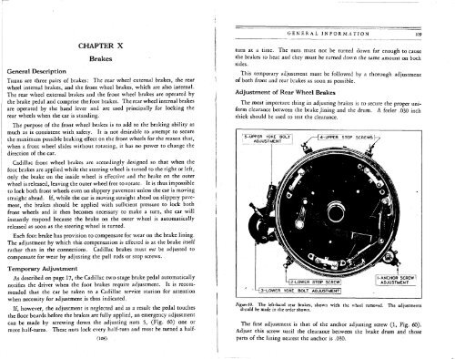
• L|3-LOWER YOkE BOLT ADJUSTMENT]<br />
ViyirtiO. The left-hand rear brakes, shown with the wheel removed. The adjustments<br />
should be made in the order shown.<br />
The first adjustment is that of the anchor adjusting screw (1, Fig. 60).<br />
Adjust this screw until the clearance between the brake drum and those<br />
parts of the lining nearest the anchor is .030.


