

1928 Cadillac - GM Heritage Center
1928 Cadillac - GM Heritage Center
1928 Cadillac - GM Heritage Center

Create successful ePaper yourself
Turn your PDF publications into a flip-book with our unique Google optimized e-Paper software.
104 CADILLAC OPERATOR'S MANUAL<br />
^^<br />
a 1<br />
r<br />
J<br />
^dl^^H<br />
With a hammer disengage the lug<br />
that locks the ends of the rim together.<br />
Then apply the rim tool, which is included<br />
in the tool equipment. This is<br />
done by hooking the U-shaped member<br />
over the lug next to the valve stem, and<br />
inserting the bolt through the holes in<br />
the lug on the other side of the split in<br />
the rim.<br />
GENERAL INFORMATION 105<br />
Caution in Adjusting Wheel Bearings<br />
The adjustment of wheel bearings or the removal of the wheels should<br />
not be attempted by one unfamiliar with work of this nature. It is recommended<br />
that the car be taken to a <strong>Cadillac</strong> service station if possible. In<br />
any event great care must be exercised in adjusting wheel bearings not to<br />
get them tight. These bearings will revolve even when adjusted very tightly,<br />
but that condition is sure to prove disastrous. They should be adjusted so<br />
that a very slight amount of play or looseness may be discerned.<br />
If, after a bearing has been adjusted to a point that is apparently correct,<br />
the locking device cannot be placed in position without changing the adjustment,<br />
it is far better to loosen the adjustment until it can be secured with the<br />
locking device than to tighten the bearing adjustment.<br />
Pull the handle of the tool up and<br />
over as far as will go, thus drawing the<br />
one end of the rim up over the other.<br />
Figure 57.<br />
The locking tongue can then be<br />
placed back of the rivet as shown, and<br />
will hold the rim in the split position.<br />
The tire can then be forced off the<br />
rim, using the "screw-driver" end of the<br />
brace wrench.<br />
After re-installing the tire, grasp the<br />
handle of the tool, disengage the locking<br />
tongue and allow the rim to return slowly<br />
to position. After removing the tool, be<br />
sure to drive the locking lug back into<br />
place.<br />
Removing tire from rim.<br />
Removing Front Wheel<br />
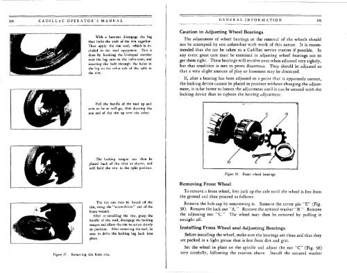
Figure 58. Front wheel bearings<br />
To remove a front wheel, first jack up the axle until the wheel is free from<br />
the ground and then proceed as follows:<br />
Remove the hub cap by unscrewing it. Remove the cotter pin "E" (Fig.<br />
58). Remove the lock nut "A." Remove the serrated washer "B." Remove<br />
the adjusting nut "C." The wheel may then be removed by pulling it<br />
straight off.<br />
Installing Front Wheel and Adjusting Bearings<br />
Before installing the wheel, make sure the bearings are clean and that they<br />
are packed in a light grease that is free from dirt and grit.<br />
Set the wheel in place on the spindle and adjust the nut "C" (Fig. 58)<br />
very carefully, following the caution above. Install the serrated washer


