

1928 Cadillac - GM Heritage Center
1928 Cadillac - GM Heritage Center
1928 Cadillac - GM Heritage Center

You also want an ePaper? Increase the reach of your titles
YUMPU automatically turns print PDFs into web optimized ePapers that Google loves.
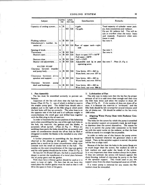
COOLING SYSTEM 43<br />
Subject<br />
<strong>Cadillac</strong><br />
341<br />
LaSalle<br />
303-328<br />
Specifications<br />
Remarks<br />
Capacity of cooling system. ..<br />
Manufacturer's number, lo-<br />
Shutters open<br />
Shutter rod adjustment,. , .<br />
WATER PUMP<br />
Clearance between impeller<br />
Clearance between drive<br />
sprocket and support<br />
Clearance between pump<br />
shaft and bushings<br />
A<br />
A<br />
A<br />
A<br />
A<br />
A<br />
A<br />
A<br />
A<br />
A<br />
A<br />
B<br />
B<br />
B<br />
B<br />
B<br />
B<br />
B<br />
B<br />
B<br />
B<br />
303<br />
303<br />
303<br />
303<br />
303<br />
303<br />
303<br />
303<br />
303<br />
303<br />
328<br />
328<br />
328<br />
328<br />
328<br />
328<br />
328<br />
328<br />
328<br />
328<br />
6 gals.<br />
5¾ gals.<br />
Rear of upper tank—right<br />
side<br />
Start to open 155°—165°F<br />
Full open— I80°F.<br />
165°—170°F.<br />
Adjustable end Y% in past<br />
operating arms.<br />
New limits, .055—.065 in.<br />
Worn limit, not over .075 in.<br />
New limits, .OO3—.0O5 in.<br />
Worn limit, not over .010 in.<br />
New limits, .001— .003 in.<br />
Worn limit, not over .006 in.<br />
Total capacity of cylinder water jackets,<br />
hose connections and radiator.<br />
Do not fill radiator full. This will result<br />
in overflow when the water heats<br />
and expands. Expensive when antifreeze<br />
is used.<br />
See note 4.<br />
See note 5.<br />
See note 6.<br />
See note 7. Plate 23, Fig. 4.<br />
1. Fan Assembly<br />
The fan must be assembled correctly to prevent unbalance.<br />
Inspection of the fan will show that the hub has two<br />
bosses (Plate 22 Fig. I), one of which is drilled to receive<br />
the smaller pump gear. The drilled boss should take a<br />
position just to the right of the filler plug at which point<br />
the bolt holes will line up correctly. The other boss is on<br />
the opposite side of the hub and is of sufficient weight to<br />
counterbalance the small gear and drilled boss together<br />
with the filler plug in the oil reservoir.<br />
In order to'maintain the correct position of the balancing<br />
parts when assembling the fan, one of the eight bolt holes in<br />
the hub, the reservoir, the gaskets and the blades, is<br />
purposely off-set A inch. (Plate 22 Fig. I). When assembling<br />
these parts the holes should line up correctly and<br />
under no consideration should the off-set hole be filed or<br />
elongated to enable the blades to be installed in any other<br />
position.<br />
A further precaution in assembling the fan should be<br />
observed in the placing of the gasket. The ring type<br />
gasket has a notch on its inner circumference which must<br />
coincide with the small oil intake hole in the hub. The<br />
notches on the outer circumference of the ring type gasket<br />
and the solid gasket should also be in line. (Plate 22 Fig. 2)<br />
On fans for 341-B and 328 cars, the hub is counterbored<br />
deeper to permit the installation of a metal plate between<br />
the oil pump gears and the gasket.<br />
With these fans a thinner gasket should be used as it is<br />
easier to keep oil tight. On fans that do not have this<br />
metal plate the thicker gasket must be used so that it will<br />
fill in the space in front of the gears.<br />
2: Lubrication of Fan<br />
The only way to make sure that the fan has the proper<br />
amount of oil is to add more than enough and then turn<br />
the filler hole down and allow the surplus to drain off.<br />
(Plate 22 Fig. 8). If the surplus oil does not drain off at<br />
once, it is because the reservoir is "air-bound," and the<br />
filler hole should be left inverted for several minutes until<br />
the oil drains out. Oil should be added to the fan every<br />
1000 miles.<br />
3. Aligning Water Pump Hose with Radiator Connection<br />
The holes for the screws by which the pump is attached<br />
to the sprocket support are purposely made A inch larger<br />
in diameter than the screws themselves. The reason for<br />
this is to permit the pump inlet connection to be lined<br />
up with the water outlet on the radiator, so that the hose<br />
will be as nearly in a straight line as possible.<br />
In order to make use of this feature the pump screws<br />
should be loosened whenever the generator chain is adjusted.<br />
Then, as the sprocket support is moved, the pump<br />
will be free to align itself.<br />
Because of the fact that the holes in the pump flange are<br />
so much larger than the screws, flat washers as well as<br />
lock washers are used under the heads of the screws.<br />
It is very important that these washers always be in place.<br />
If they are omitted, the screws will bottom against the<br />
chain housing, instead of clamping the pump to the face<br />
of the sprocket support. This would tend to pry the<br />
support away from the chain housing and cause an oil leak.<br />
If a water pump is removed for any reason the flat<br />
washers must be reinstalled.<br />
#


