Retinal Prosthesis Dissertation - Student Home Pages
Retinal Prosthesis Dissertation - Student Home Pages
Retinal Prosthesis Dissertation - Student Home Pages
Create successful ePaper yourself
Turn your PDF publications into a flip-book with our unique Google optimized e-Paper software.
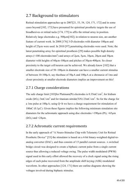
2.7 Background to stimulators<br />
<strong>Retinal</strong> stimulation approaches up to 2007[21, 53, 54, 124, 171, 172] and in some<br />
cases beyond [102, 173] have presumed for epiretinal prosthetic targets the use of<br />
bioadhesives or retinal tacks [174, 175] to affix the retinal array in position.<br />
Relatively large electrodes e.g. 500µm[102]; in relation to neuron size, are another<br />
feature of current work. In 2008 [176] 3-D electrodes with diameter 100µm and<br />
height of 25µm were used. In 2010 [97] penetrating electrodes were used. Note; the<br />
latest penetrating array for epiretinal prosthesis [29] makes possible high density<br />
arrays (≈100 electrodes/mm 2 ) and arrays of 2µm, 5µm, 10µm, 20µm and 30µm<br />
diameter with heights of 60µm-100µm and pitches of 50µm-400µm. So closer<br />
proximity to the target cell/neuron can be achieved. We already know [102] that a<br />
smaller electrode size of 50–100µm in diameter can have a smaller current stimulus<br />
of between 10-100µA; say rheobase of 50µA and 100µA at a chronaxie of 1ms and<br />
closer proximity at smaller electrode diameters implies an improvement on this!<br />
2.7.1 Charge considerations<br />
The safe charge limit [103]for Platinum(Pt) electrodes is 0.35mC/cm 2 , for Iridium<br />
oxide (IrO x ) 3mC/cm 2 and for titanium nitride(TiN) 23mC/cm 2 . So for the charge for<br />
a 1ms pulse at 100µA; using Q=It we have a charge requirement for stimulation of<br />
100nC (0.1µC). Given these figures implies the following minimum simulation site<br />
diameters for the achromatic approach using disc electrodes ≈190µm (Pt), ≈65µm<br />
(IrO x ) and ≈24µm.<br />
2.7.2 Achromatic current requirements<br />
In the early approach of “A Neuro-Stimulus Chip with Telemetry Unit for <strong>Retinal</strong><br />
Prosthetic Device” [53] the stimulator is based on a 4-bit binary-weighted digital-toanalog<br />
converter (DAC), and thus consists of 15 parallel current sources. A switched<br />
bridge circuit was designed to create a biphasic current pulse from a single current<br />
source thus allowing a reduced voltage swing. The pulse width modulated (PWM)<br />
signal used in this early effort allowed the recovery of a clock signal using the rising<br />
edges of each pulse recovered from the amplitude shift keying (ASK) modulated<br />
waveform. In other approaches [124, 171] there are outline diagrams showing the<br />
voltages involved during biphasic stimulus.<br />
49 of 200


