1 Montgomery Modular Multiplication in Hard- ware
1 Montgomery Modular Multiplication in Hard- ware
1 Montgomery Modular Multiplication in Hard- ware

You also want an ePaper? Increase the reach of your titles
YUMPU automatically turns print PDFs into web optimized ePapers that Google loves.
FEI KEMT<br />
clock<br />
<strong>in</strong>put<br />
F IN<br />
F FB<br />
Phase<br />
Detector<br />
+/-<br />
Delay<br />
L<strong>in</strong>e<br />
clock<br />
output<br />
F OUT<br />
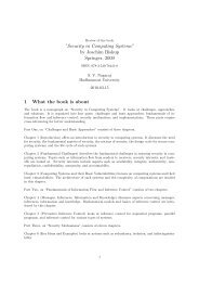
Figure 6 – 2 Block diagram of digital DLL unit typical for Xil<strong>in</strong>x FPGA clock management<br />
circuits<br />
The DLL achieves very good results <strong>in</strong> delay compensation and clock condition-<br />
<strong>in</strong>g. However, the available range of clock dividers is much more limited than <strong>in</strong><br />
case of PLL. It is possible to use an output p<strong>in</strong> with clock signal derived from <strong>in</strong>put<br />
signal, where its frequency may be doubled or divided by values: 1.5, 2, 2.5, 3, 4, 5,<br />
8, or 16 <strong>in</strong> case of Spartan II FPGA devices [127].<br />
6.1.1 PLL as Source of Randomness<br />
Due to its digital nature the DLL <strong>in</strong> Xil<strong>in</strong>x devices is less sensible to noise envi-<br />
ronment than analog PLL with VCO. The VCO tends to lock to frequencies of<br />
disturb<strong>in</strong>g external signals and therefore is required a use of separated networks for<br />
power supply and ground connection mounted only to the clock circuitry. On the<br />
other hand, the analog PLL makes possible a small area implementation provid<strong>in</strong>g<br />
a wide range of clock frequencies. The DLL technology is limited <strong>in</strong> this direction<br />
and offers only certa<strong>in</strong> comb<strong>in</strong>ations of ratios between <strong>in</strong>put and output frequencies.<br />
Changes <strong>in</strong> the temperature or fluctuations of the supply voltage correlated to<br />
switch<strong>in</strong>g activity of the closely placed logic may cause a drift <strong>in</strong> the generated<br />
clock signal. As a compensation the loop makes adjustments of the delay elements<br />
or VCO frequency what is recognised as a determ<strong>in</strong>istic jitter added to the clock<br />
signal. Other source of noise <strong>in</strong>fluenc<strong>in</strong>g the PLL circuitry is the <strong>in</strong>put clock signal.<br />
Therefore there is a tradeoff between compensation of the <strong>in</strong>ternal or external jitter.<br />
All phase changes <strong>in</strong> the PLL or differences of delays <strong>in</strong> the DLL <strong>in</strong>troduce a<br />
jitter <strong>in</strong> the synthesised output signal. Filters <strong>in</strong>side the clock circuitry are matched<br />
to elim<strong>in</strong>ate the non-l<strong>in</strong>earity caused by the loop and external <strong>in</strong>fluences, however<br />
the <strong>in</strong>tr<strong>in</strong>sic random noise of the VCO is always present <strong>in</strong> the output clock signal<br />
and cannot be attenuated completely. Thanks to that, the PLL provides a promis<strong>in</strong>g<br />
source of randomness suitable for an implementation of the TRNG. In addition, the<br />
96