1 Montgomery Modular Multiplication in Hard- ware
1 Montgomery Modular Multiplication in Hard- ware
1 Montgomery Modular Multiplication in Hard- ware

Create successful ePaper yourself
Turn your PDF publications into a flip-book with our unique Google optimized e-Paper software.
FEI KEMT<br />
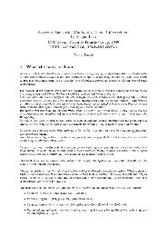
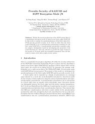
x i x i-1 xi-n+1<br />
Y (j)<br />
M (j)<br />
S (j)<br />
PE 1<br />
Y (j-1)<br />
M (j-1)<br />
S (j-1)<br />
PE 2<br />
S (j-n)<br />
data<br />
memory<br />
. . .<br />
. . .<br />
. . .<br />
Y (j-n+1)<br />
M (j-n+1)<br />
S (j-n+1)<br />
PE n<br />
Figure 2 – 5 Pipel<strong>in</strong>ed organization of the MMM coprocessor based on n-stage PEs connection<br />
and separated embedded data memory<br />
The maximum degree of pipel<strong>in</strong>e that can be obta<strong>in</strong>ed with this architecture is<br />
found as:<br />
nmax =<br />
� �<br />
e + 1<br />
2<br />
(2.3)<br />
The number 2 <strong>in</strong> denom<strong>in</strong>ator expresses the number of clock cycles after which the<br />
output of the MMM unit is valid. It means also that new values for <strong>in</strong>put variables<br />
of the PEs <strong>in</strong> the pipel<strong>in</strong>ed row are delivered every third clock cycle. Output data<br />
from one stage are kept between the adjacent stages <strong>in</strong> temporal registers for one<br />
clock cycle and afterwards delivered to the subsequent stage. The stages <strong>in</strong>clude the<br />
second register at their <strong>in</strong>put level which provides total delay of two clock cycles as<br />
required by the computation process.<br />
To keep the <strong>in</strong>ternal control logic simple the number of the stages n is restricted<br />
to values divid<strong>in</strong>g the number of words e (n|e). Thanks to the simplification <strong>in</strong> the<br />
moment when the computation had been f<strong>in</strong>ished the last word of the sum S is at<br />
the output of the last unit <strong>in</strong> the row and is directly shifted to the memory to be<br />
stored there. In case of arbitrary n the functionality for a word shift between the<br />
stages at the end of computations would need to be implemented. Addition of the<br />
feature requires some extra logic <strong>in</strong> the data-path what has a negative <strong>in</strong>fluence on<br />
the maximal clock frequency, therefore it is not supported <strong>in</strong> our designs.<br />
The number of clock cycles needed for a s<strong>in</strong>gle MMM operation <strong>in</strong> design con-<br />
ta<strong>in</strong><strong>in</strong>g n ≤ nmax MMM units can be computed as:<br />
TMMM = k2<br />
+ 2n =<br />
wn<br />
� �<br />
ew<br />
e + 2n (2.4)<br />
n<br />
From the Equation 2.4 we can see that the number of stages n has a significant<br />
impact on computation time and reduces it l<strong>in</strong>early. When less than nmax MMM<br />
30