1 Montgomery Modular Multiplication in Hard- ware
1 Montgomery Modular Multiplication in Hard- ware
1 Montgomery Modular Multiplication in Hard- ware

You also want an ePaper? Increase the reach of your titles
YUMPU automatically turns print PDFs into web optimized ePapers that Google loves.
FEI KEMT<br />
2.2.3 Interface to Controller<br />
The way <strong>in</strong> which the MMM coprocessor is connected to the control unit (e.g. an<br />
embedded processor) is important for the control of the computation process and<br />
for the exchange of processed data.<br />
Our first objective is to f<strong>in</strong>d a solution which would make possible a fast and flex-<br />
ible replacement of <strong>in</strong>put and output data between the memory of the host processor<br />
and the MMM coprocessor’s <strong>in</strong>ternal memory block. The requirement for flexibility<br />
is related to the scalability of the coprocessor that may <strong>in</strong>clude several MMM units.<br />
Moreover, the <strong>in</strong>ternal word widths of the control unit and the coprocessor may<br />
differ.<br />
Other goal is to optimise the control of the coprocessor(s). The trigger<strong>in</strong>g of<br />
the computations and then check<strong>in</strong>g their status plays important role especially <strong>in</strong><br />
configurations with several coprocessors (not necessarily the MMM coprocessors)<br />
operated by one control unit when it is <strong>in</strong>eligible to block the operations runn<strong>in</strong>g on<br />
the host processor.<br />
F<strong>in</strong>ally, the goal is also to design an <strong>in</strong>terface that would be universal and ap-<br />
plicable with m<strong>in</strong>imal amount of a clue logic for connection to different types of<br />
processor buses.<br />
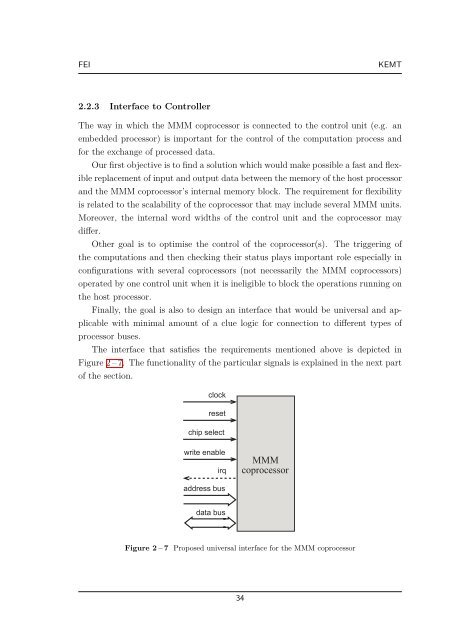
The <strong>in</strong>terface that satisfies the requirements mentioned above is depicted <strong>in</strong><br />
Figure 2 – 7. The functionality of the particular signals is expla<strong>in</strong>ed <strong>in</strong> the next part<br />
of the section.<br />
clock<br />
reset<br />
chip select<br />
write enable<br />
irq<br />
address bus<br />
data bus<br />
MMM<br />
coprocessor<br />
Figure 2 – 7 Proposed universal <strong>in</strong>terface for the MMM coprocessor<br />
34