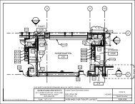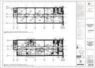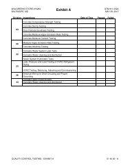
DSLBD Office Fit Out - Broughton Construction Company
DSLBD Office Fit Out - Broughton Construction Company
DSLBD Office Fit Out - Broughton Construction Company

You also want an ePaper? Increase the reach of your titles
YUMPU automatically turns print PDFs into web optimized ePapers that Google loves.
1. Where studs are installed directly against exterior walls, install foam-gasket isolation strip between studs and<br />
wall.<br />
B. Extend partition framing full height to structural supports or substrates above suspended ceilings, except where<br />
partitions are indicated to terminate at suspended ceilings. Continue framing over frames for doors and openings<br />
and frame around ducts penetrating partitions above ceiling to provide support for gypsum board.<br />
1. For fire-resistance-rated and STC-rated partitions that extend to the underside of floor/roof slabs and decks<br />
or other continuous solid-structure surfaces to obtain ratings, install framing around structural and other<br />
members extending below floor/roof slabs and decks, as needed to support gypsum board closures and to<br />
make partitions continuous from floor to underside of solid structure.<br />
a. Terminate partition framing at suspended ceilings where indicated.<br />
C. Install steel studs so flanges point in the same direction and leading edge or end of each panel can be attached to<br />
open (unsupported) edges of stud flanges first.<br />
D. Curved Partitions:<br />
1. Cut top and bottom track (runners) through leg and web at 2-inch (50-mm) intervals for arc length. In cutting<br />
lengths of track, allow for uncut straight lengths of not less than 12 inches (300 mm) at ends of arcs.<br />
2. Bend track to uniform curve and locate straight lengths so they are tangent to arcs.<br />
3. Support outside (cut) leg of track by clinching steel sheet strip, 1-inch- (25-mm-) high-by-thickness of track<br />
metal, to inside of cut legs using metal lock fasteners.<br />
4. Begin and end each arc with a stud, and space intermediate studs equally along arcs at stud spacing<br />
recommended in writing by gypsum board manufacturer for radii indicated. On straight lengths of not less<br />
than 2 studs at ends of arcs, place studs 6 inches (150 mm) o.c.<br />
E. Frame door openings to comply with GA-600 and with gypsum board manufacturer's applicable written<br />
recommendations, unless otherwise indicated. Screw vertical studs at jambs to jamb anchor clips on door frames;<br />
install runner track section (for cripple studs) at head and secure to jamb studs.<br />
1. Install two studs at each jamb, unless otherwise indicated.<br />
F. Z-Furring Members:<br />
1. Erect insulation vertically and hold in place with Z-furring members spaced 24 inches (610 mm) o.c.<br />
2. Except at exterior corners, securely attach narrow flanges of furring members to wall with concrete stub nails,<br />
screws designed for masonry attachment, or powder-driven fasteners spaced 24 inches (600 mm) o.c.<br />
3. At exterior corners, attach wide flange of furring members to wall with short flange extending beyond corner;<br />
on adjacent wall surface, screw-attach short flange of furring channel to web of attached channel. At interior<br />
corners, space second member no more than 12 inches (300 mm) from corner and cut insulation to fit.<br />
3.6 INSTALLING SHAFT WALL ASSEMBLIES<br />
A. General: Install gypsum board shaft-wall assemblies to comply with requirements of fire-resistance-rated assemblies<br />
indicated, manufacturer's written installation instructions.<br />
B. Do not bridge building expansion joints with shaft-wall assemblies; frame both sides of joints with furring and other<br />
support.<br />
C. Install supplementary framing in gypsum board shaft-wall assemblies around openings and as required for blocking,<br />
bracing, and support of gravity and pullout loads of fixtures, equipment, services, heavy trim, furnishings, and similar<br />
items that cannot be supported directly by shaft-wall assembly framing.<br />
1. Where handrails directly attach to gypsum board shaft-wall assemblies, provide galvanized steel reinforcing<br />
strip with 0.0312-inch (0.79-mm) minimum thickness of base (uncoated) metal, accurately positioned and<br />
secured behind at least 1 face-layer panel.<br />
GYPSUM BOARD ASSEMBLIES 09 21 16 - 9