- Page 1 and 2: THÈSE En vue de l'obtention du DOC
- Page 3: Acknowledgements i ACKNOWLEDGEMENTS
- Page 6 and 7: iv Table of Contents 3.4 Generic ML
- Page 8 and 9: vi Table of Contents 7.1 General mo
- Page 10 and 11: viii Résumé français (French sum
- Page 12 and 13: x Résumé français (French summar
- Page 14 and 15: xii Résumé français (French summ
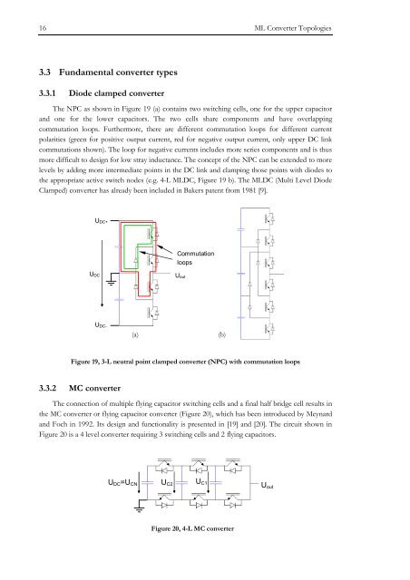
- Page 16 and 17: xiv Résumé français (French summ
- Page 18 and 19: xvi Résumé français (French summ
- Page 20 and 21: xviii Résumé français (French su
- Page 22 and 23: Introduction 1 2 INTRODUCTION This
- Page 24 and 25: Introduction 3 tighter capacitor di
- Page 26 and 27: Introduction 5 TABLE 1, OPERATING R
- Page 28 and 29: Introduction 7 2.3 Glossary Note th
- Page 30 and 31: Introduction 9 2.4 Nomenclature Not
- Page 32 and 33: Introduction 11 DPC DSP DTC FC FPGA
- Page 34 and 35: ML Converter Topologies 13 3 ML CON
- Page 38 and 39: ML Converter Topologies 17 Each swi
- Page 40 and 41: ML Converter Topologies 19 size doe
- Page 42 and 43: ML Converter Topologies 21 plus (a)
- Page 44 and 45: ML Converter Topologies 23 N >= 2,
- Page 46 and 47: ML Converter Topologies 25 (a) (b)
- Page 48 and 49: ML Converter Topologies 27 (a) (b)
- Page 50 and 51: ML Converter Topologies 29 In a pra
- Page 52 and 53: ML Converter Topologies 31 reality,
- Page 54 and 55: ML Converter Topologies 33 All cons
- Page 56 and 57: ML Converter Topologies 35 TABLE 16
- Page 58 and 59: ML Converter Topologies 37 TABLE 17
- Page 60 and 61: ML Converter Topologies 39 3.7.4.1
- Page 62 and 63: ML Converter Topologies 41 f C sw =
- Page 64 and 65: ML Converter Topologies 43 A second
- Page 66 and 67: ML Converter Topologies 45 Limitati
- Page 68 and 69: ML Converter Topologies 47 1 K M 2
- Page 70: ML Converter Topologies 49 3.8 Exec
- Page 73 and 74: 52 3-L DC Link ML Converter Propert
- Page 75 and 76: 54 3-L DC Link ML Converter Propert
- Page 77 and 78: 56 3-L DC Link ML Converter Propert
- Page 79 and 80: 58 3-L DC Link ML Converter Propert
- Page 81 and 82: 60 3-L DC Link ML Converter Propert
- Page 83 and 84: 62 3-L DC Link ML Converter Propert
- Page 85 and 86: 64 3-L DC Link ML Converter Propert
- Page 87 and 88:
66 3-L DC Link ML Converter Propert
- Page 89 and 90:
68 3-L DC Link ML Converter Propert
- Page 91 and 92:
70 3-L DC Link ML Converter Propert
- Page 93 and 94:
72 3-L DC Link ML Converter Propert
- Page 95 and 96:
74 3-L DC Link ML Converter Propert
- Page 97 and 98:
76 3-L DC Link ML Converter Propert
- Page 99 and 100:
78 3-L DC Link ML Converter Propert
- Page 101 and 102:
80 3-L DC Link ML Converter Propert
- Page 103 and 104:
82 3-L DC Link ML Converter Propert
- Page 105 and 106:
84 3-L DC Link ML Converter Propert
- Page 107 and 108:
86 3-L DC Link ML Converter Propert
- Page 110 and 111:
NP Control with Carrier based PWM 8
- Page 112 and 113:
NP Control with Carrier based PWM 9
- Page 114 and 115:
NP Control with Carrier based PWM 9
- Page 116 and 117:
NP Control with Carrier based PWM 9
- Page 118 and 119:
NP Control with Carrier based PWM 9
- Page 120 and 121:
NP Control with Carrier based PWM 9
- Page 122 and 123:
NP Control with Carrier based PWM 1
- Page 124 and 125:
NP Control with Carrier based PWM 1
- Page 126 and 127:
NP Control with Carrier based PWM 1
- Page 128 and 129:
NP Control with Carrier based PWM 1
- Page 130 and 131:
NP Control with Carrier based PWM 1
- Page 132 and 133:
NP Control with Carrier based PWM 1
- Page 134 and 135:
NP Control with Carrier based PWM 1
- Page 136 and 137:
NP Control with Carrier based PWM 1
- Page 138 and 139:
NP Control with Carrier based PWM 1
- Page 140 and 141:
NP Control with Carrier based PWM 1
- Page 142 and 143:
NP Control with Carrier based PWM 1
- Page 144 and 145:
NP Control with Optimal Sequence SV
- Page 146 and 147:
NP Control with Optimal Sequence SV
- Page 148 and 149:
NP Control with Optimal Sequence SV
- Page 150 and 151:
NP Control with Optimal Sequence SV
- Page 152 and 153:
NP Control with Optimal Sequence SV
- Page 154 and 155:
NP Control with Optimal Sequence SV
- Page 156 and 157:
NP Control with Optimal Sequence SV
- Page 158 and 159:
NP Control with Optimal Sequence SV
- Page 160 and 161:
NP Control with Optimal Sequence SV
- Page 162 and 163:
NP Control with Optimal Sequence SV
- Page 164 and 165:
NP Control with Optimal Sequence SV
- Page 166 and 167:
NP Control with Optimal Sequence SV
- Page 168 and 169:
NP Control with Optimal Sequence SV
- Page 170 and 171:
Application and Verification 149 7
- Page 172 and 173:
Application and Verification 151 TA
- Page 174 and 175:
Application and Verification 153 Th
- Page 176 and 177:
Application and Verification 155 7.
- Page 178 and 179:
Application and Verification 157 7.
- Page 180 and 181:
Application and Verification 159 7.
- Page 182 and 183:
Application and Verification 161 TA
- Page 184 and 185:
Application and Verification 163 7.
- Page 186 and 187:
Application and Verification 165 TA
- Page 188:
Application and Verification 167 7.
- Page 191 and 192:
170 Conclusions and Outlook 8.1.2 M
- Page 193 and 194:
172 Conclusions and Outlook 8.2 Out
- Page 195 and 196:
174 Conclusions and Outlook 8.3 Sum
- Page 197 and 198:
176 Appendix I = 1− ) (99) ( C 2
- Page 199 and 200:
178 Appendix TABLE 78, FLYING CAPAC
- Page 201 and 202:
180 Appendix 9.3 Single phase NP cu
- Page 203 and 204:
182 Appendix 9.4 States of the ANPC
- Page 205 and 206:
184 Appendix 9.5 NP currents as a f
- Page 207 and 208:
186 Appendix 9.5.3 Maximum and mini
- Page 209 and 210:
188 Appendix 9.6 NP current functio
- Page 211 and 212:
190 Appendix TABLE 91, NP CURRENT I
- Page 213 and 214:
192 Appendix TABLE 93, NP CURRENT I
- Page 216 and 217:
Bibliography 195 10 BIBLIOGRAPHY [1
- Page 218 and 219:
Bibliography 197 [33] P. Steimer,
- Page 220 and 221:
Bibliography 199 neutral point bala
- Page 222 and 223:
Bibliography 201 [88] J. Pou, J. Za