

Christoph Haederli - Les thèses en ligne de l'INP - Institut National ...
Christoph Haederli - Les thèses en ligne de l'INP - Institut National ...
Christoph Haederli - Les thèses en ligne de l'INP - Institut National ...

You also want an ePaper? Increase the reach of your titles
YUMPU automatically turns print PDFs into web optimized ePapers that Google loves.
28 ML Converter Topologies<br />
3.6.1 Operation of the ANPC 1 variation with backward half bridge<br />
The topology in Figure 31 (a) has a special feature making it interesting for implem<strong>en</strong>tation:<br />
The transition from upper to lower DC link and vice versa does not have to be done with a 2 level<br />
commutation as in the ANPC 1 but can be done with a commutation in the half bridge on the<br />
flying capacitor facing the DC link. This results in a very smooth glitch free operation of the<br />
converter (as is also the case for the SMC).<br />
(a) (b) (c) (d) (e)<br />
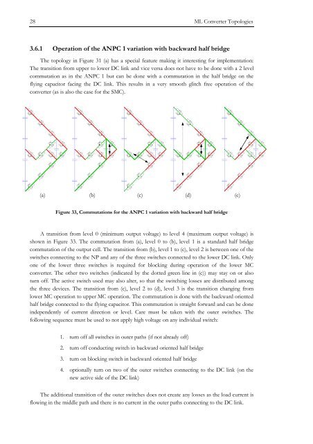
Figure 33, Commutations for the ANPC 1 variation with backward half bridge<br />
A transition from level 0 (minimum output voltage) to level 4 (maximum output voltage) is<br />
shown in Figure 33. The commutation from (a), level 0 to (b), level 1 is a standard half bridge<br />
commutation of the output cell. The transition from (b), level 1 to (c), level 2 is betwe<strong>en</strong> one of the<br />
switches connecting to the NP and any of the three switches connected to the lower DC link. Only<br />
one of the lower three switches is required for blocking during operation of the lower MC<br />
converter. The other two switches (indicated by the dotted gre<strong>en</strong> line in (c)) may stay on or also<br />
turn off. The active switch used may also alter, so that the switching losses are distributed among<br />
the three <strong>de</strong>vices. The transition from (c), level 2 to (d), level 3 is the transition changing from<br />
lower MC operation to upper MC operation. The commutation is done with the backward ori<strong>en</strong>ted<br />
half bridge connected to the flying capacitor. This commutation is straight forward and can be done<br />
in<strong>de</strong>p<strong>en</strong>d<strong>en</strong>tly of curr<strong>en</strong>t direction or level. Care must be tak<strong>en</strong> with the outer switches. The<br />
following sequ<strong>en</strong>ce must be used to not apply high voltage on any individual switch:<br />
1. turn off all switches in outer paths (if not already off)<br />
2. turn off conducting switch in backward ori<strong>en</strong>ted half bridge<br />
3. turn on blocking switch in backward ori<strong>en</strong>ted half bridge<br />
4. optionally turn on two of the outer switches connecting to the DC link (on the<br />
new active si<strong>de</strong> of the DC link)<br />
The additional transition of the outer switches does not create any losses as the load curr<strong>en</strong>t is<br />
flowing in the middle path and there is no curr<strong>en</strong>t in the outer paths connecting to the DC link.


