Christoph Haederli - Les thèses en ligne de l'INP - Institut National ...
Christoph Haederli - Les thèses en ligne de l'INP - Institut National ...
Christoph Haederli - Les thèses en ligne de l'INP - Institut National ...
Create successful ePaper yourself
Turn your PDF publications into a flip-book with our unique Google optimized e-Paper software.
24 ML Converter Topologies<br />
will charge and discharge simultaneously and the capacitor voltages stay balanced thanks to the<br />
symmetry of the AC output curr<strong>en</strong>t. Additional control schemes are required to comp<strong>en</strong>sate for<br />
unbalance g<strong>en</strong>erated by any source of disturbance. Such schemes can be found in literature and are<br />
not subject of this thesis.<br />
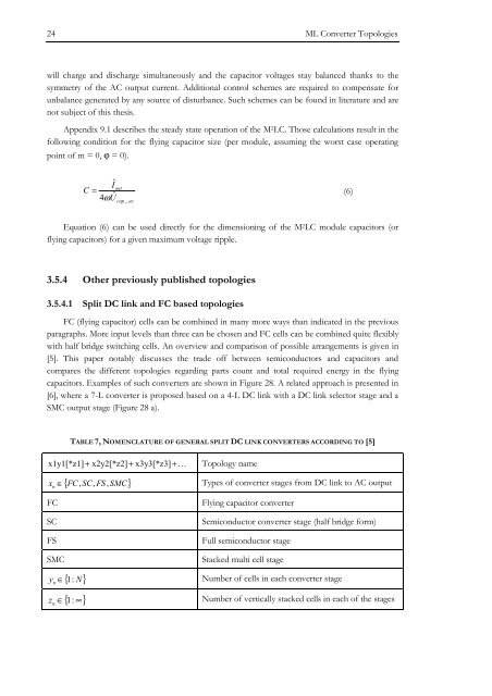
App<strong>en</strong>dix 9.1 <strong>de</strong>scribes the steady state operation of the M 2 LC. Those calculations result in the<br />
following condition for the flying capacitor size (per module, assuming the worst case operating<br />
point of m = 0, ϕ = 0).<br />
C<br />
Iˆ<br />
4ωUˆ<br />
out<br />
= (6)<br />
cap _ ac<br />
Equation (6) can be used directly for the dim<strong>en</strong>sioning of the M 2 LC module capacitors (or<br />
flying capacitors) for a giv<strong>en</strong> maximum voltage ripple.<br />
3.5.4 Other previously published topologies<br />
3.5.4.1 Split DC link and FC based topologies<br />
FC (flying capacitor) cells can be combined in many more ways than indicated in the previous<br />
paragraphs. More input levels than three can be chos<strong>en</strong> and FC cells can be combined quite flexibly<br />
with half bridge switching cells. An overview and comparison of possible arrangem<strong>en</strong>ts is giv<strong>en</strong> in<br />
[5]. This paper notably discusses the tra<strong>de</strong> off betwe<strong>en</strong> semiconductors and capacitors and<br />
compares the differ<strong>en</strong>t topologies regarding parts count and total required <strong>en</strong>ergy in the flying<br />
capacitors. Examples of such converters are shown in Figure 28. A related approach is pres<strong>en</strong>ted in<br />
[6], where a 7-L converter is proposed based on a 4-L DC link with a DC link selector stage and a<br />
SMC output stage (Figure 28 a).<br />
TABLE 7, NOMENCLATURE OF GENERAL SPLIT DC LINK CONVERTERS ACCORDING TO [5]<br />
x1y1[*z1] + x2y2[*z2] + x3y3[*z3] +… Topology name<br />
{ FC , SC,<br />
FS SMC}<br />
x n<br />
∈ ,<br />
Types of converter stages from DC link to AC output<br />
FC<br />
SC<br />
FS<br />
Flying capacitor converter<br />
Semiconductor converter stage (half bridge form)<br />
Full semiconductor stage<br />
SMC<br />
Stacked multi cell stage<br />
{ 1 N}<br />
y n<br />
∈ :<br />
Number of cells in each converter stage<br />
{ 1 ∞}<br />
z ∈ :<br />
Number of vertically stacked cells in each of the stages<br />
n


