Christoph Haederli - Les thèses en ligne de l'INP - Institut National ...
Christoph Haederli - Les thèses en ligne de l'INP - Institut National ...
Christoph Haederli - Les thèses en ligne de l'INP - Institut National ...
Create successful ePaper yourself
Turn your PDF publications into a flip-book with our unique Google optimized e-Paper software.
ML Converter Topologies 23<br />
N >= 2, M >= 2<br />
N M<br />
G<strong>en</strong>eralized ML<br />
ANPC<br />
A higher number of output levels are available. The<br />
smallest step possible at the output is smaller than the<br />
lowest capacitor voltage. Such small steps can only be<br />
achieved by simultaneous commutations. Non<br />
optimum modulation schemes have to be used in the<br />
case of single commutations.<br />
3.5.3 Modular multi level converter M 2 LC<br />
The M 2 LC [17] applies two converter branches per phase leg, one connecting to the positive<br />
supply and one connecting to the negative supply. Both branches are ma<strong>de</strong> of switched capacitors<br />
that can either be series connected or bypassed, thus g<strong>en</strong>erating a controllable DC voltage. Both<br />
branches can g<strong>en</strong>erate the same output voltages and are applied simultaneously. If full bridges<br />
instead of half bridges are used in the two branches, an AC input voltage can be applied. Direct ML<br />
AC/AC conversion based on such casca<strong>de</strong>d H-bridges has be<strong>en</strong> proposed by Erickson [23], and by<br />
Glinka and Marquardt [24].<br />
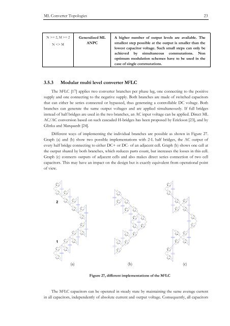
Differ<strong>en</strong>t ways of implem<strong>en</strong>ting the individual branches are possible as shown in Figure 27.<br />
Graph (a) and (b) show two possible implem<strong>en</strong>tations with 2-L half bridges, the AC output of<br />
every half bridge connecting to either DC+ or DC- of an adjac<strong>en</strong>t cell. Graph (b) shows one cell at<br />
the output shared by both branches, which reduces parts count, but increases the losses in this cell.<br />
Graph (c) connects outputs of adjac<strong>en</strong>t cells and also makes direct series connection of two cell<br />
capacitors. This may have an impact on the <strong>de</strong>sign but is exactly equival<strong>en</strong>t from operational point<br />
of view.<br />
2<br />
1<br />
(a) (b) (c)<br />
Figure 27, differ<strong>en</strong>t implem<strong>en</strong>tations of the M 2 LC<br />
The M 2 LC capacitors can be operated in steady state by maintaining the same average curr<strong>en</strong>t<br />
in all capacitors, in<strong>de</strong>p<strong>en</strong>d<strong>en</strong>tly of absolute curr<strong>en</strong>t and output voltage. Consequ<strong>en</strong>tly, all capacitors


