

Christoph Haederli - Les thèses en ligne de l'INP - Institut National ...
Christoph Haederli - Les thèses en ligne de l'INP - Institut National ...
Christoph Haederli - Les thèses en ligne de l'INP - Institut National ...

Create successful ePaper yourself
Turn your PDF publications into a flip-book with our unique Google optimized e-Paper software.
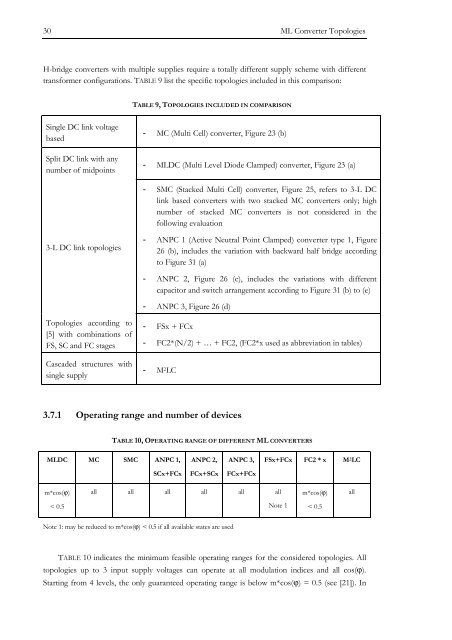
30 ML Converter Topologies<br />
H-bridge converters with multiple supplies require a totally differ<strong>en</strong>t supply scheme with differ<strong>en</strong>t<br />
transformer configurations. TABLE 9 list the specific topologies inclu<strong>de</strong>d in this comparison:<br />
TABLE 9, TOPOLOGIES INCLUDED IN COMPARISON<br />
Single DC link voltage<br />
based<br />
Split DC link with any<br />
number of midpoints<br />
- MC (Multi Cell) converter, Figure 23 (b)<br />
- MLDC (Multi Level Dio<strong>de</strong> Clamped) converter, Figure 23 (a)<br />
- SMC (Stacked Multi Cell) converter, Figure 25, refers to 3-L DC<br />
link based converters with two stacked MC converters only; high<br />
number of stacked MC converters is not consi<strong>de</strong>red in the<br />
following evaluation<br />
3-L DC link topologies<br />
- ANPC 1 (Active Neutral Point Clamped) converter type 1, Figure<br />
26 (b), inclu<strong>de</strong>s the variation with backward half bridge according<br />
to Figure 31 (a)<br />
- ANPC 2, Figure 26 (c), inclu<strong>de</strong>s the variations with differ<strong>en</strong>t<br />
capacitor and switch arrangem<strong>en</strong>t according to Figure 31 (b) to (e)<br />
- ANPC 3, Figure 26 (d)<br />
Topologies according to<br />
[5] with combinations of<br />
FS, SC and FC stages<br />
Casca<strong>de</strong>d structures with<br />
single supply<br />
- FSx + FCx<br />
- FC2*(N/2) + … + FC2, (FC2*x used as abbreviation in tables)<br />
- M 2 LC<br />
3.7.1 Operating range and number of <strong>de</strong>vices<br />
TABLE 10, OPERATING RANGE OF DIFFERENT ML CONVERTERS<br />
MLDC MC SMC ANPC 1,<br />
ANPC 2,<br />
ANPC 3,<br />
FSx+FCx FC2 * x M 2 LC<br />
SCx+FCx<br />
FCx+SCx<br />
FCx+FCx<br />
m*cos(ϕ)<br />
all all all all all all<br />
m*cos(ϕ)<br />
all<br />
< 0.5<br />
Note 1<br />
< 0.5<br />
Note 1: may be reduced to m*cos(ϕ) < 0.5 if all available states are used<br />
TABLE 10 indicates the minimum feasible operating ranges for the consi<strong>de</strong>red topologies. All<br />
topologies up to 3 input supply voltages can operate at all modulation indices and all cos(ϕ).<br />
Starting from 4 levels, the only guaranteed operating range is below m*cos(ϕ) = 0.5 (see [21]). In


