

Christoph Haederli - Les thèses en ligne de l'INP - Institut National ...
Christoph Haederli - Les thèses en ligne de l'INP - Institut National ...
Christoph Haederli - Les thèses en ligne de l'INP - Institut National ...

Create successful ePaper yourself
Turn your PDF publications into a flip-book with our unique Google optimized e-Paper software.
20 ML Converter Topologies<br />
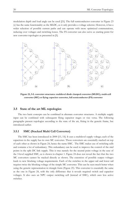
modulation <strong>de</strong>pth and load angle can be used [21]. The full semiconductor converter in Figure 23<br />
(c) has the same functionality as the MLDC, as it only provi<strong>de</strong>s a voltage selector. However, it has a<br />
wi<strong>de</strong>r selection of possible curr<strong>en</strong>t paths and can operate with more optimized commutations,<br />
reducing over voltages and switching losses. The FS converter can also serve as starting point for<br />
new converter topologies as pres<strong>en</strong>ted in [5].<br />
(a) (b) (c)<br />
Figure 23, 5-L converter structures: multilevel dio<strong>de</strong> clamped converter (MLDC), multi-cell<br />
converter (MC) or flying capacitor converter, full semiconductor (FS) converter<br />
3.5 State of the art ML topologies<br />
The two basic concepts can be combined in alternate converter structures. A multiple supply<br />
input can be combined with subsequ<strong>en</strong>t flying capacitor stages or vice versa. The following<br />
paragraphs pres<strong>en</strong>t topologies according to the state of the art, fitting in the g<strong>en</strong>eric frame, but<br />
introduced earlier.<br />
3.5.1 SMC (Stacked Multi Cell Converter)<br />
The SMC has be<strong>en</strong> introduced in 2000 [13, 15]. It uses a multilevel supply voltage; each of the<br />
capacitors in the supply has its own MC converter. Those converters are ess<strong>en</strong>tially stacked on top<br />
of each other as shown in Figure 24, h<strong>en</strong>ce the name SMC. The SMC makes use of switching cells<br />
and contains a lot of redundancy. This redundancy can be used to improve the control of the mid<br />
points in the split DC link supply. This is true namely for the neutral point voltage in the case of<br />
the 3-level supplied SMC, as is shown in chapter 1. Figure 24 does not reveal the fact that the two<br />
MC converters cannot be stacked directly as shown. The ext<strong>en</strong>sion of possible output voltages<br />
leads to new blocking voltage requirem<strong>en</strong>ts. Each of the switches in the upper rail and lower rail<br />
requires twice the blocking voltage of the simple MC converter. This can be se<strong>en</strong> much better wh<strong>en</strong><br />
using the g<strong>en</strong>eric repres<strong>en</strong>tation in triangle form (Figure 25). This converter is ess<strong>en</strong>tially the same<br />
as the one in Figure 24, with the only differ<strong>en</strong>ce that it reveals required switch and capacitor<br />
voltages. It also uses an NPC output switching cell (instead of SMC), which uses less active<br />
switches.


