

Christoph Haederli - Les thèses en ligne de l'INP - Institut National ...
Christoph Haederli - Les thèses en ligne de l'INP - Institut National ...
Christoph Haederli - Les thèses en ligne de l'INP - Institut National ...

You also want an ePaper? Increase the reach of your titles
YUMPU automatically turns print PDFs into web optimized ePapers that Google loves.
18 ML Converter Topologies<br />
3.4 G<strong>en</strong>eric ML VSC framework<br />
ML converters can be built based on multiple differ<strong>en</strong>t switching cells, connecting them in<br />
various differ<strong>en</strong>t ways. A large number of differ<strong>en</strong>t approaches are possible, leading to numerous<br />
differ<strong>en</strong>t topologies. Ev<strong>en</strong> though several differ<strong>en</strong>t types of switching cells are used, it is possible to<br />
pres<strong>en</strong>t most ML-VSC topologies in one g<strong>en</strong>eric framework based on g<strong>en</strong>erically connected<br />
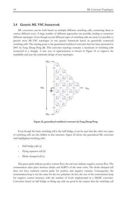
switching cells. The starting point is the g<strong>en</strong>eralized multilevel converter that has be<strong>en</strong> pres<strong>en</strong>ted in<br />
2001 by Fang Zh<strong>en</strong>g P<strong>en</strong>g [8]. This converter topology contains a maximum of switching cells<br />
connected in a triangle. A new way of repres<strong>en</strong>tation is chos<strong>en</strong> in Figure 21 to improve the<br />
readability and ease the systematic <strong>de</strong>sign of new topologies.<br />
U DC+<br />
U DC<br />
U out<br />
U DC-<br />
Figure 21, g<strong>en</strong>eralized multilevel converter by Fang Zh<strong>en</strong>g P<strong>en</strong>g<br />
Ev<strong>en</strong> though the basic switching cell is the half bridge, it can be se<strong>en</strong> that the other two types<br />
of switching cells are also hidd<strong>en</strong> in that structure. Figure 22 shows the g<strong>en</strong>eralized ML converter<br />
with highlighted switching cells:<br />
- Half bridge cells (a)<br />
- Flying capacitor cell (b)<br />
- Dio<strong>de</strong> clamped cell (c)<br />
The gre<strong>en</strong> paths indicate positive curr<strong>en</strong>t flow; the red ones indicate negative curr<strong>en</strong>t flow. The<br />
commutation takes place betwe<strong>en</strong> dio<strong>de</strong>s and IGBT’s of the same color. The dio<strong>de</strong> clamped cell<br />
does not have common curr<strong>en</strong>t paths for positive and negative curr<strong>en</strong>ts. Consequ<strong>en</strong>tly, the<br />
commutation loop is not the same for the two polarities. In fact, the size of the commutation loop<br />
for negative curr<strong>en</strong>t increases with the number of levels implem<strong>en</strong>ted in a MLDC converter.<br />
Converters based on half bridge or flying cap cells are good in the respect that the switching cell


