- Page 1 and 2:
AMBA Design KitRevision: r3p0Techni
- Page 3 and 4:
ContentsAMBA Design Kit Technical R
- Page 5 and 6:
List of TablesAMBA Design Kit Techn
- Page 7 and 8:
List of TablesTable 4-23 WDOGPERIPH
- Page 9 and 10:
List of FiguresAMBA Design Kit Tech
- Page 11 and 12:
List of FiguresFigure 4-24 PrimeCel
- Page 13 and 14:
PrefaceThis preface introduces the
- Page 15 and 16:
PrefaceAppendix A AHB-Lite Overview
- Page 17 and 18:
PrefaceNumberingThe numbering conve
- Page 19 and 20:
Chapter 1IntroductionThis chapter d
- Page 21 and 22:
Introduction1.2 AMBA signalsThis se
- Page 23 and 24:
IntroductionSignalDirectionSlave Ma
- Page 25 and 26:
Introduction1.3 Product revisionsTh
- Page 27 and 28:
Chapter 2Functional OverviewThis ch
- Page 29 and 30:
Functional Overview2.2 ADK componen
- Page 32 and 33:
Functional OverviewPrimeCell Genera
- Page 34 and 35:
Functional Overview• MuxS2M• Re
- Page 36 and 37:
Functional Overview• AHB2:— EgM
- Page 38 and 39:
Functional Overview• Decoder• M
- Page 40 and 41:
Functional OverviewAddressNormal me
- Page 42 and 43:
AHB Components• 64-bit to 32-bit
- Page 44 and 45:
AHB Components3.2 ArbiterThe AMBA b
- Page 46 and 47:
AHB Components3.2.2 Signal descript
- Page 48 and 49: AHB Components3.4 Master-to-slave m
- Page 50 and 51: AHB Components3.6 Example retry sla
- Page 52 and 53: AHB Components3.7.1 SMI programmer
- Page 54 and 55: AHB ComponentsTest vector typesThe
- Page 56 and 57: AHB ComponentsThe address increment
- Page 58 and 59: AHB ComponentsTable 3-7 Signal desc
- Page 60 and 61: AHB Components3.8 Bus matrixThis se
- Page 62 and 63: AHB ComponentsThe two products are
- Page 64 and 65: AHB Components Figure 3-8 BusMatrix
- Page 66 and 67: AHB ComponentsNoteWhen connecting t
- Page 68 and 69: AHB Components• If the Bus Matrix
- Page 70 and 71: AHB ComponentsINCR bursts are treat
- Page 72 and 73: AHB ComponentsFigure 3-11 on page 3
- Page 74 and 75: AHB Components3.8.10 Signal descrip
- Page 76 and 77: AHB ComponentsTable 3-8 Bus Matrix
- Page 78 and 79: AHB ComponentsAddress0xFFFFFFFF0xF0
- Page 80 and 81: AHB Components3.10 APB bridgeThe AH
- Page 82 and 83: AHB Components3.10.2 AhbToAPB bridg
- Page 84 and 85: AHB Components3.11 Example bus mast
- Page 86 and 87: AHB ComponentsConfigurable optionsT
- Page 88 and 89: AHB ComponentsAhb2Ahb (1:1)This is
- Page 90 and 91: AHB ComponentsTrial synthesis of th
- Page 92 and 93: AHB ComponentsAHB1AHBdecoder 1A[31:
- Page 94 and 95: AHB Componentsconfirmation of compl
- Page 96 and 97: AHB ComponentsMaster cancelspending
- Page 100 and 101: AHB Components3.13 Asynchronous AHB
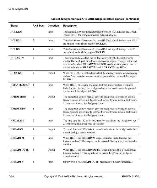
- Page 102 and 103: AHB ComponentsTable 3-13 Asynchrono
- Page 104 and 105: AHB ComponentsTable 3-13 Asynchrono
- Page 106 and 107: AHB ComponentsSlave responsesLocked
- Page 108 and 109: AHB ComponentsThe nonvectored and d
- Page 110 and 111: AHB Components7. Clear the interrup
- Page 112 and 113: AHB ComponentsBits Name FunctionIRQ
- Page 114 and 115: AHB ComponentsBits Name FunctionSof
- Page 116 and 117: AHB ComponentsDefault Vector Addres
- Page 118 and 119: AHB ComponentsTable 3-30 lists the
- Page 120 and 121: AHB ComponentsPeripheral Identifica
- Page 122 and 123: AHB ComponentsPrimeCell Identificat
- Page 124 and 125: AHB ComponentsSignal Type Direction
- Page 126 and 127: AHB ComponentsDownsizer transfersTh
- Page 128 and 129: AHB ComponentsUnsupported transfers
- Page 130 and 131: AHB ComponentsTable 3-43 Signal map
- Page 132 and 133: AHB ComponentsInstead of reading HR
- Page 134 and 135: AHB ComponentsThe funnel can only f
- Page 136 and 137: AHB Components3-96 Copyright © 200
- Page 138 and 139: APB Components4.1 Remap and pause c
- Page 140 and 141: APB ComponentsReset Status Clear Re
- Page 142 and 143: APB ComponentsPeripheral Identifica
- Page 144 and 145: APB ComponentsPrimeCell Identificat
- Page 146 and 147: APB ComponentsThe functionality of
- Page 148 and 149:
APB Components4.3 Peripheral to bri
- Page 150 and 151:
APB Components4.4.1 Programmer’s
- Page 152 and 153:
APB ComponentsWatchdog Raw Interrup
- Page 154 and 155:
APB ComponentsWatchdog Integration
- Page 156 and 157:
APB ComponentsNoteWhen you design a
- Page 158 and 159:
APB ComponentsThe four, 8-bit Prime
- Page 160 and 161:
APB Components4.5 Dual input timerT
- Page 162 and 163:
APB Componentsbackground load value
- Page 164 and 165:
APB Components• TIMCLKENx is tied
- Page 166 and 167:
APB ComponentsCurrent Value Registe
- Page 168 and 169:
APB ComponentsTable 4-31 lists the
- Page 170 and 171:
APB ComponentsTable 4-34 lists the
- Page 172 and 173:
APB ComponentsPeripheral Identifica
- Page 174 and 175:
APB ComponentsPrimeCell Identificat
- Page 176 and 177:
APB Components4-40 Copyright © 200
- Page 178 and 179:
Behavioral Models5.1 External RAM,T
- Page 180 and 181:
Behavioral Models5.2 Internal memor
- Page 182 and 183:
Behavioral Models5.3 External ROMTh
- Page 184 and 185:
Behavioral Models5.5 AHB file reade
- Page 186 and 187:
Behavioral ModelsThe following AHB-
- Page 188 and 189:
Behavioral ModelsIf HREADY is asser
- Page 190 and 191:
Behavioral ModelsCycle n Cycle n+1C
- Page 192 and 193:
Behavioral ModelsCycle 1 Cycle 2Com
- Page 194 and 195:
Behavioral ModelsThis sequence perf
- Page 196 and 197:
Behavioral ModelsTable 5-7 Stimulus
- Page 198 and 199:
Behavioral ModelsField Default Valu
- Page 200 and 201:
Behavioral ModelsInput stimulusfile
- Page 202 and 203:
Behavioral ModelsEndiannessThe prep
- Page 204 and 205:
Behavioral ModelsTable 5-13 fm2conv
- Page 206 and 207:
Behavioral ModelsTable 5-16 Numberi
- Page 208 and 209:
Behavioral Models5.6 Test interface
- Page 210 and 211:
Behavioral Models5.6.2 User-defined
- Page 212 and 213:
PrimeCell GPIO6.1 OperationThe Prim
- Page 214 and 215:
PrimeCell GPIO6-4 Copyright © 2003
- Page 216 and 217:
AHB-Lite OverviewA.1 About AHB-Lite
- Page 218 and 219:
AHB-Lite OverviewTable A-1 AHB-Lite
- Page 220 and 221:
AHB-Lite OverviewA.3 AHB-Lite slave
- Page 222 and 223:
GlossaryAdvanced Peripheral Bus (AP
- Page 224 and 225:
Glossaryaddresses cause accesses to
- Page 226:
GlossaryGlossary-6 Copyright © 200


