1 Surgery CAMLOG Compendium
1 Surgery CAMLOG Compendium
1 Surgery CAMLOG Compendium

You also want an ePaper? Increase the reach of your titles
YUMPU automatically turns print PDFs into web optimized ePapers that Google loves.
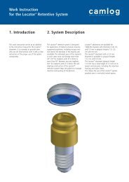
<strong>Surgery</strong> Manual<br />
SCREW-LINE Insertion<br />
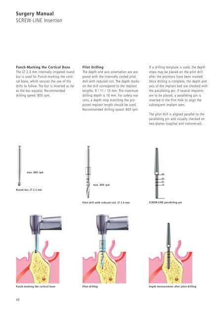
Punch-Marking the Cortical Bone<br />
The Ø 2.3 mm internally irrigated round<br />
bur is used for Punch-marking the cortical<br />
bone, which secures the use of the<br />
drills to follow. The bur is inserted as far<br />
as the bur equator. Recommended<br />
drilling speed: 800 rpm.<br />
Round bur, Ø 2.3 mm<br />
46<br />
max. 800 rpm<br />
Punch-marking the cortical bone Pilot drilling<br />
Pilot Drilling<br />
The depth and axis orientation are prepared<br />
with the internally cooled pilot<br />
drill with reduced coil. The depth marks<br />
on the drill correspond to the implant<br />
lengths: 9 / 11 / 13 mm. The maximum<br />
drilling depth is 16 mm. For safety reasons,<br />
a depth stop matching the proposed<br />
implant length should be used.<br />
Recommended drilling speed: 800 rpm.<br />
max. 800 rpm<br />
Pilot drill with reduced coil, Ø 2.0 mm<br />
If a drilling template is used, the depth<br />
stops may be placed on the pilot drill<br />
after the positions have been marked.<br />
Once drilling is complete, the depth and<br />
axis of the implant bed are checked with<br />
the paralleling pin. If several implants<br />
are to be placed, a paralleling pin is<br />
inserted in the first hole to align the<br />
subsequent implant axes.<br />
The pilot drill is aligned parallel to the<br />
paralleling pin and visually checked on<br />
two planes (sagittal and transversal).<br />
SCREW-LINE paralleling pin<br />
Depth measurement after pilot drilling