1 Surgery CAMLOG Compendium
1 Surgery CAMLOG Compendium
1 Surgery CAMLOG Compendium

You also want an ePaper? Increase the reach of your titles
YUMPU automatically turns print PDFs into web optimized ePapers that Google loves.
<strong>Surgery</strong> Manual<br />
SCREW-LINE Insertion<br />
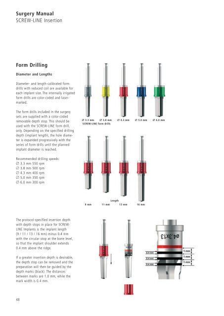
Form Drilling<br />
Diameter and Lengths<br />
Diameter- and length-calibrated form<br />
drills with reduced coil are available for<br />
each implant size. The internally irrigated<br />
form drills are color-coded and lasermarked.<br />
The form drills included in the surgery<br />
sets are supplied with a color-coded<br />
removable depth stop. This should be<br />
used with the SCREW-LINE form drill,<br />
only. Depending on the specified drilling<br />
depth (implant length), the hole diameter<br />
is expanded progressively with the<br />
series of form drills until the planned<br />
implant diameter is reached.<br />
Recommended drilling speeds:<br />
Ø 3.3 mm 550 rpm<br />
Ø 3.8 mm 500 rpm<br />
Ø 4.3 mm 400 rpm<br />
Ø 5.0 mm 350 rpm<br />
Ø 6.0 mm 300 rpm<br />
The protocol-specified insertion depth<br />
with depth stops in place for SCREW-<br />
LINE Implants is the implant length<br />
(9 / 11 / 13 / 16 mm) minus 0.4 mm<br />
with the circular stop at the bone level,<br />
so that the implant shoulder extends<br />
0.4 mm above the ridge.<br />
If a greater insertion depth is desirable,<br />
the depth stop can be removed and the<br />
preparation will then be guided by the<br />
depth marks (black). The distances<br />
between marks are 1.0 mm, while the<br />
mark width is 0.4 mm.<br />
48<br />
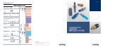
Ø 3.3 mm Ø 3.8 mm Ø 4.3 mm Ø 5.0 mm Ø 6.0 mm<br />
SCREW-LINE form drills<br />
Length<br />
9 mm 11 mm 13 mm 16 mm