Catalog PM 21 2013 - Siemens Industry, Inc.
Catalog PM 21 2013 - Siemens Industry, Inc.
Catalog PM 21 2013 - Siemens Industry, Inc.

Create successful ePaper yourself
Turn your PDF publications into a flip-book with our unique Google optimized e-Paper software.
© <strong>Siemens</strong> AG <strong>2013</strong><br />
SINAMICS S120 drive system<br />
Line Modules and line-side components<br />
Active Line Modules in booksize format<br />
Active Interface Modules<br />
■ Integration<br />
L3 L2 L1<br />
Active Interface<br />
Module<br />
PE<br />
1)<br />
DO<br />
CU<br />
Active Line Module<br />
<br />
T1<br />
T2<br />
1<br />
2<br />
3<br />
4<br />
X1<strong>21</strong><br />
Fan off<br />
X<strong>21</strong><br />
1<br />
2<br />
3<br />
4<br />
+ Temp<br />
- Temp<br />
DCP<br />
DCN<br />
DC link current<br />
3<br />
W2 V2 U2<br />
+<br />
+<br />
-<br />
-<br />
X124<br />
+<br />
M<br />
ext.<br />
24 V<br />
U1<br />
V1<br />
W1<br />
PE<br />
PE<br />
G_D<strong>21</strong>1_EN_00190a<br />
1) Digital input (DI) or digital output (DO), controlled via Control Unit.<br />
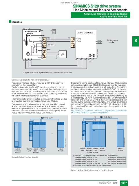
Connection example for Active Interface Module<br />
The Active Interface Module requires a 24 V DC supply for<br />
operation of the integral fan.<br />
The fan rotates after the 24 V DC supply is applied and can, if<br />
necessary (service life, noise), be shut off fom the Control Unit<br />
over the "Fan off" input. It is only permitted to switch off the fan<br />
when the infeed of the drive system is not operating, otherwise<br />
the Active Interface Module will overheat.<br />
The thermostatic switch installed in the Active Interface Module<br />
is evaluated over the connected Active Line Module.<br />
The power cables between the Active Interface Module and<br />
Active Line Module must be shielded if limit values for interference<br />
suppression are to be complied with. The cable shield<br />
can be routed over the shield connection plate (option) to the<br />
Active Interface Module or Active Line Module.<br />
Depending on the position of the Active Interface Module in the<br />
drive system, additional DRIVE-CLiQ cables may be required.<br />
If it is separately installed next to the left side of the Control Unit<br />
and Active Line Module, no additional DRIVE-CLiQ cables are<br />
required. If the Active Interface Module is placed between the<br />
Control Unit and Active Line Module, the DRIVE-CLiQ cables<br />
supplied with the Active Line Modules are suitable for setting up<br />
a line topology, i.e. Active Line Module and all Motor Modules in<br />
series on one DRIVE-CLiQ line. If the Active Line Module is connected<br />
over a separate DRIVE-CLiQ line, the DRIVE-CLiQ cable<br />
marked with (1) must be ordered. A DRIVE-CLiQ cable suitable<br />
for connection (2) is included in the scope of supply of the Active<br />
Line Module.<br />
For DRIVE-CLiQ cables for different configurations, see chapter<br />
MOTION-CONNECT connection systems).<br />
DRIVE-CLiQ<br />
(1)<br />
(2)<br />
DRIVE-CLiQ<br />
. . .<br />
. . .<br />
Active<br />
Interface<br />
Module<br />
Control<br />
Unit<br />
Active<br />
Line<br />
Module<br />
Motor<br />
Module<br />
Motor<br />
Module<br />
G_D<strong>21</strong>1_EN_00191c<br />
Control<br />
Unit<br />
Active Active<br />
Interface Line<br />
Module Module<br />
Motor<br />
Module<br />
Motor<br />
Module<br />
G_D<strong>21</strong>1_EN_00192c<br />
Separate Active Interface Module<br />
(1) DRIVE-CLiQ cable between Control Unit and Motor Module<br />
Active Interface Module 16 kW:<br />
0.31 m (see Accessories)<br />
Active Interface Module 36 kW:<br />
0.41 m (see Accessories)<br />
Active Interface Module 55 kW:<br />
0.60 m (see Accessories)<br />
Active Interface Module 80 kW and 120 kW: 0.95 m (see Accessories)<br />
(2) <strong>Inc</strong>luded in scope of supply of Active Line Modules<br />
Active Interface Module integrated in the drive line-up<br />
<strong>Siemens</strong> <strong>PM</strong> <strong>21</strong> · <strong>2013</strong><br />
3/117