Catalog PM 21 2013 - Siemens Industry, Inc.
Catalog PM 21 2013 - Siemens Industry, Inc.
Catalog PM 21 2013 - Siemens Industry, Inc.

Create successful ePaper yourself
Turn your PDF publications into a flip-book with our unique Google optimized e-Paper software.
© <strong>Siemens</strong> AG <strong>2013</strong><br />
SINAMICS S120 drive system<br />
Line Modules and line-side components<br />
Smart Line Modules in booksize format<br />
■ Overview<br />
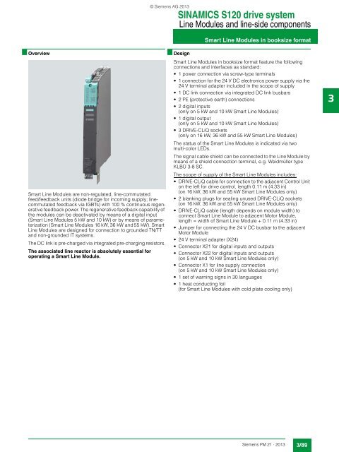
Smart Line Modules are non-regulated, line-commutated<br />
feed/feedback units (diode bridge for incoming supply; linecommutated<br />
feedback via IGBTs) with 100 % continuous regenerative<br />
feedback power. The regenerative feedback capability of<br />
the modules can be deactivated by means of a digital input<br />
(Smart Line Modules 5 kW and 10 kW) or by means of parameterization<br />
(Smart Line Modules 16 kW, 36 kW and 55 kW). Smart<br />
Line Modules are designed for connection to grounded TN/TT<br />
and non-grounded IT systems.<br />
The DC link is pre-charged via integrated pre-charging resistors.<br />
The associated line reactor is absolutely essential for<br />
operating a Smart Line Module.<br />
■ Design<br />
Smart Line Modules in booksize format feature the following<br />
connections and interfaces as standard:<br />
• 1 power connection via screw-type terminals<br />
• 1 connection for the 24 V DC electronics power supply via the<br />
24 V terminal adapter included in the scope of supply<br />
• 1 DC link connection via integrated DC link busbars<br />
• 2 PE (protective earth) connections<br />
• 2 digital inputs<br />
(only on 5 kW and 10 kW Smart Line Modules)<br />
• 1 digital output<br />
(only on 5 kW and 10 kW Smart Line Modules)<br />
• 3 DRIVE-CLiQ sockets<br />
(only on 16 kW, 36 kW and 55 kW Smart Line Modules)<br />
The status of the Smart Line Modules is indicated via two<br />
multi-color LEDs.<br />
The signal cable shield can be connected to the Line Module by<br />
means of a shield connection terminal, e.g. Weidmüller type<br />
KLBÜ 3-8 SC.<br />
The scope of supply of the Smart Line Modules includes:<br />
• DRIVE-CLiQ cable for connection to the adjacent Control Unit<br />
on the left for drive control, length 0.11 m (4.33 in)<br />
(on 16 kW, 36 kW and 55 kW Smart Line Modules only)<br />
• 2 blanking plugs for sealing unused DRIVE-CLiQ sockets<br />
(on 16 kW, 36 kW and 55 kW Smart Line Modules only)<br />
• DRIVE-CLiQ cable (length depends on module width) to<br />
connect Smart Line Module to adjacent Motor Module,<br />
length = width of Smart Line Module + 0.11 m (4.33 in)<br />
• Jumper for connecting the 24 V DC busbar to the adjacent<br />
Motor Module<br />
• 24 V terminal adapter (X24)<br />
• Connector X<strong>21</strong> for digital inputs and outputs<br />
• Connector X22 for digital inputs and outputs<br />
(on 5 kW and 10 kW Smart Line Modules only)<br />
• Connector X1 for line supply connection<br />
(on 5 kW and 10 kW Smart Line Modules only)<br />
• 1 set of warning signs in 30 languages<br />
• 1 heat conducting foil<br />
(for Smart Line Modules with cold plate cooling only)<br />
3<br />
<strong>Siemens</strong> <strong>PM</strong> <strong>21</strong> · <strong>2013</strong><br />
3/89